

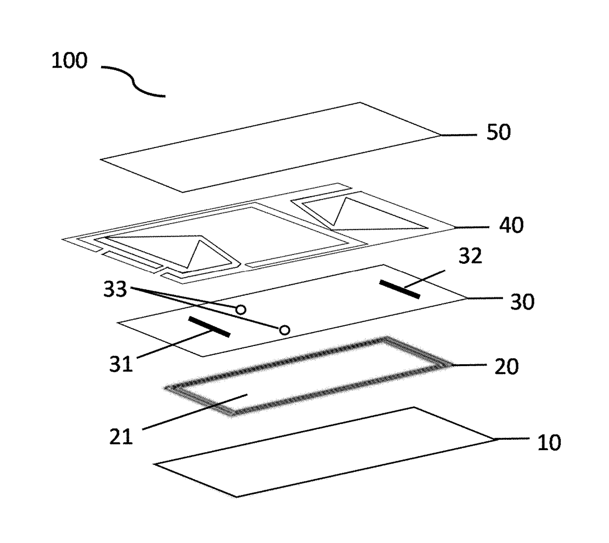
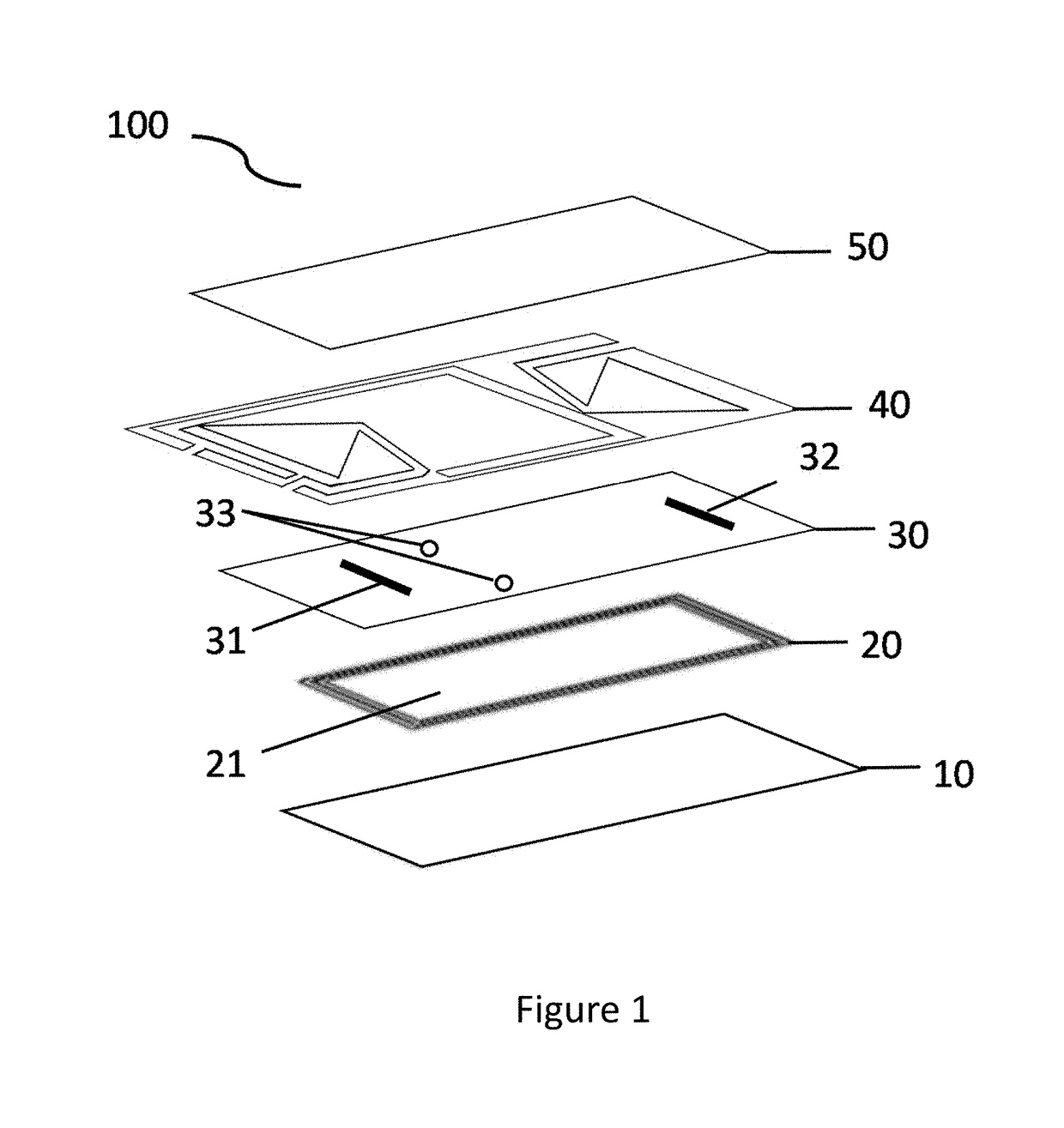
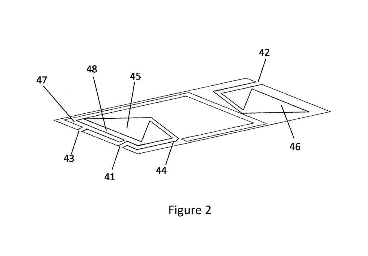
Microfluidic bio-reactor device
a microfluidic and cell culture technology, applied in bioreactors/fermenters, biochemical apparatus and processes, biomass after-treatment, etc., can solve the problems of harsh stem cells, difficult culture technology, and in vivo cell behavior and properties of conventional culture methods,
- Summary
- Abstract
- Description
- Claims
- Application Information
AI Technical Summary
Benefits of technology
Problems solved by technology
Method used
Image

Examples
example 1
, the Cell Properties of Mouse Mesenchymal Stem Cells (MSCs) in the Microfluidic Bio-Reactor Device of the Present Invention
[0108]Mouse MSCs were harvested from the bone marrow of postnatal 7-week old C57BL / 6J mice (National Laboratory Animal Center, Taipei, Taiwan). The mouse MSCs were cultured in the 6-cm culture dish (BD Falcon) and the microfluidic bio-reactor device of the present invention. The mouse MSCs were maintained in Dulbecco's Modified Eagle's Medium (LG-DMEM, Sigma-Aldrich, St. Louis, Mo., USA) and the flow rate was 940 μl / hr.
[0109]Please refer to the FIG. 8, the upper row is the result in the 6-cm culture dish and lower row is the result in the microfluidic bio-reactor device of the present invention. In day 0-3, the morphology of the MSCs is similar in both microfluidic bio-reactor device of the present invention and culture dish. Also, as shown in FIG. 9, the growth curve of MSCs is similar in both environments after 9 days of culturing. Further, the expressions of...
example 2
, the Cell Properties of Human Mesenchymal Stem Cells (MSCs) in the Microfluidic Bio-Reactor Device of the Present Invention
[0110]The human mesenchymal stem cells were purchased from Lonza (Walkersville, Md., #PT-2501). The human MSCs were cultured in the 6-cm culture dish (BD Falcon) and the microfluidic bio-reactor device of the present invention. The human MSCs were maintained in Iscove's modified Dulbecco's medium (IMDM, Gibco BRL, Grand Island, N.Y., USA) and the flow rate is 940 □l / hr. Please refer to FIG. 11, the star sign represents the statistic significant difference. In day 0-9, the growth rate of human MSCs in the microfluidic bio-reactor device of the present invention is better than in the culture dish. Further, the expressions of cell surface markers of human MSCs in the microfluidic bio-reactor device of the present invention and culture dish were analyzed by flow cytometry. As shown in FIG. 12, the human MSCs cultivated in both environments expressed the standard su...
example 3
Properties of the Human Embryonic Stem Cells (ESCs) and the Human Induced Pluripotent Stem Cells (iPSCs) in the Microfluidic Bio-Reactor Device of the Present Invention
[0111]The human embryonic stem cells (ESCs) GE09 (National Institutes of Health, USA) and human induced pluripotent stem cells (iPSCs) CFB46 (Y C. Huang H P, Chen H F, Chen P H, Chuang C Y, Lin S J, “Factors from human embryonic stem cell-derived fibroblast-like) were cultured in the 6-cm culture dish (BD Falcon) and the microfluidic bio-reactor device of the present invention. The human ESCs and iPSCs were maintained in Dulbecco's Modified Eagle's Medium (LG-DMEM, Sigma-Aldrich, St. Louis, Mo., USA) and the flow rate is 1100 μl / hr. Please refer to FIG. 13 and FIG. 14, the star sign represents the statistic significant difference. In day 0-3, the growth rate of the human ESCs (FIG. 13) and the human iPSCs (FIG. 14) in the microfluidic bio-reactor device of the present invention are better than the cells in the culture...
PUM
| Property | Measurement | Unit |
|---|---|---|
| thickness | aaaaa | aaaaa |
| flow rate | aaaaa | aaaaa |
| flow rate | aaaaa | aaaaa |
Abstract
Description
Claims
Application Information