Brake by-wire control system

a control system and brake technology, applied in the field of vehicle control systems, can solve the problems of increased increased cost and complexity associated with triple redundancy among control modules, and disadvantages of added cost and system complexity, so as to reduce the number of controllers and control modules, enhance redundancy and fault tolerance, and reduce system complexity

Inactive Publication Date: 2005-10-13
GENERAL MOTORS COMPANY
View PDF25 Cites 31 Cited by
  • Summary
  • Abstract
  • Description
  • Claims
  • Application Information

AI Technical Summary

Benefits of technology

[0006] The present invention comprises a brake control system and control architecture which provides system level redundancy and fault tolerance with reduced system complexity, particularly a reduced number of controllers and control modules as compared to previous brake control systems.
[0007] The key features of the control system and architecture of the present invention are flexibility and simplicity. The architecture is flexible enough to allow front / rear pair braking which is frequently desirable for use in cars, as well as diagonal pair braking which is frequently desirable for use in trucks. The simplicity stems from the fact that three controllers are used to achieve two fail-silent pairs of controllers through the sharing of one monitoring controller. The system also features a mechanism whereby the monitoring controller ensures fault tolerance and the fail-silent operation of the brake control units if an undesired event occurs in either of the supervisory controllers or the communication buses which provide signal communication between the supervisory controllers and the brake controls.
[0008] The control system also features additional redundancy with regard to the brake command signals. The system utilizes three raw brake pedal sensor signals to produce a processed brake command signal as is known. However, each one of the three raw brake command signals is also provided to one of the three controllers together with the processed brake command signal, thereby enabling enhanced redundancy and fault tolerance with respect to the determination of the brake command signal.

Problems solved by technology

However; such systems also typically remove any direct mechanical or hydraulic force transmitting path between the vehicle operator and the brake control units.
While the system shown in FIG. 1 provides a generally acceptable level of redundancy and fault tolerance with regard to single point events, the cost and system complexity associated with dual controllers and dual control modules remains undesirably high.
This design generally provides a greater degree of redundancy and fault tolerance with regard to undesired events associated with the controllers; however, it also has the same disadvantage of the added cost and system complexity associated with dual controllers as the design of FIG. 1, and even greater cost and complexity associated with triple redundancy among the control modules.

Method used


Image

  • Brake by-wire control system
  • Brake by-wire control system
  • Brake by-wire control system

Examples


Embodiment Construction

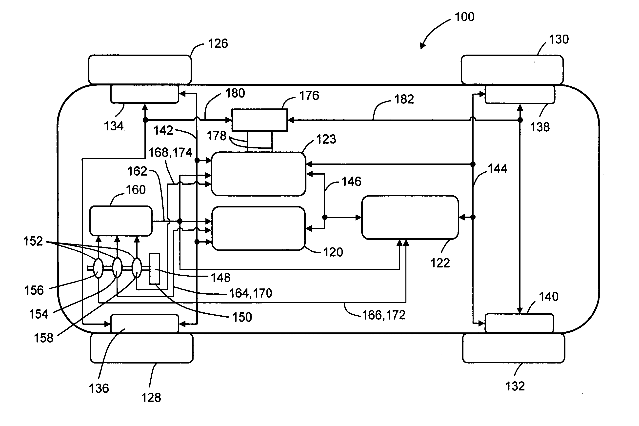
[0015]FIG. 3 illustrates an embodiment of a brake by wire brake control system 100 of the present invention. Described generally, brake control system 100 and its constituent parts comprise a fail-silent brake control system, such that it either provides the correct brake control command and result at the correct time, or it provides no control result at all. Brake control system 100 generally comprises two substantially identical supervisory brake controllers 120,122 and a monitoring controller 123. Controllers 120,122,123 may be incorporated into a single controller as separate control modules or portions thereof. However, it is believed to be preferred to implement controllers 120,122,123 as shown in FIG. 3 as separate and distinct controllers or control modules to provide additional protection against common mode events. Each of supervisory controllers 120,122 is adapted to control the braking of a pair of road wheels 126,128,130,132. The embodiment shown in FIG. 3 illustrates a...


PUM


Abstract

A brake control system for brake by wire applications having a dual fail-silent pair controller architecture. The system utilizes two supervisory controllers and a shared monitoring controller to achieve the dual fail-silent pair configuration. The brake control system also features a mechanism whereby the monitoring controller ensures the fail-silent operation of the brake control units in the event of certain undesired events occurring within the system by assuming control of the affected brake control units. The control system further assures that no single event, including an event related to the monitoring controller, causes loss of more than half the braking functionality. The control system also features additional redundancy with regard to the brake command signals by sharing a separate unprocessed brake command signal with each of the supervisory controllers and the monitoring controller.

Description

TECHNICAL FIELD [0001] This invention generally relates to vehicle control systems. More particularly, this invention relates to fault-tolerant by-wire vehicle control systems. Most particularly, this invention relates to fault-tolerant by-wire brake control systems. BACKGROUND OF THE INVENTION [0002] Brake by wire brake control systems provide a number of advantages with regard to brake system packaging. The associated electronic control systems and the implementation of advanced computer control algorithms facilitate a number of new brake control features. However; such systems also typically remove any direct mechanical or hydraulic force transmitting path between the vehicle operator and the brake control units. Therefore, much attention has been given to designing brake by wire brake control systems and control architectures that ensure robust operation. General design techniques which have been employed in such systems are redundancy, fault tolerance to undesired events (e.g.,...

Claims


Application Information

Patent Timeline
Patent Type & Authority Applications(United States)
IPC IPC(8): B60T8/00B60T8/32B60T8/88B60T13/66B60T13/74B60T17/22
CPCB60T8/321B60T8/885B60T13/74B60T2270/404B60T2270/413
Inventor NAIK, SANJEEV M.MISHRA, PRADYUMNA K.FUHRMAN, THOMAS E.HOWELL, MARK N.DEBOUK, RAMI I.SALMAN, MUTASIM A.
Owner GENERAL MOTORS COMPANY
Why Eureka
Try Eureka