Oled microcavity subpixels and color filter elements

Active Publication Date: 2005-10-13
GLOBAL OLED TECH
View PDF18 Cites 219 Cited by
  • Summary
  • Abstract
  • Description
  • Claims
  • Application Information

AI Technical Summary

Benefits of technology

[0007] It is therefore an object of the present invention to reduce apparent color shift

Problems solved by technology

However, devices constructed with microcavities suffer from the problem t

Method used


Image

  • Oled microcavity subpixels and color filter elements
  • Oled microcavity subpixels and color filter elements
  • Oled microcavity subpixels and color filter elements

Examples


Example

EXAMPLE

[0030] The present invention is explained more specifically with reference to the following example.

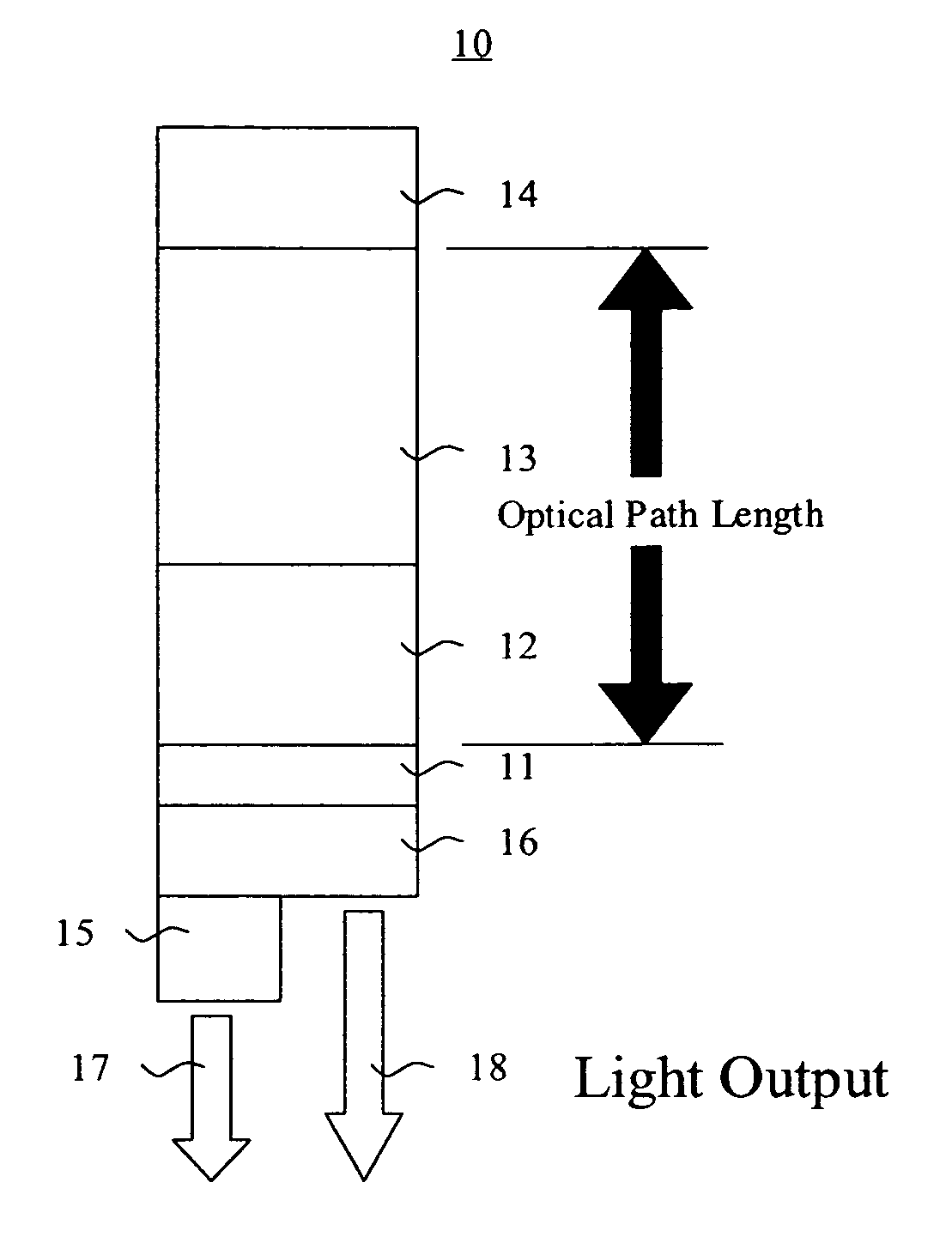
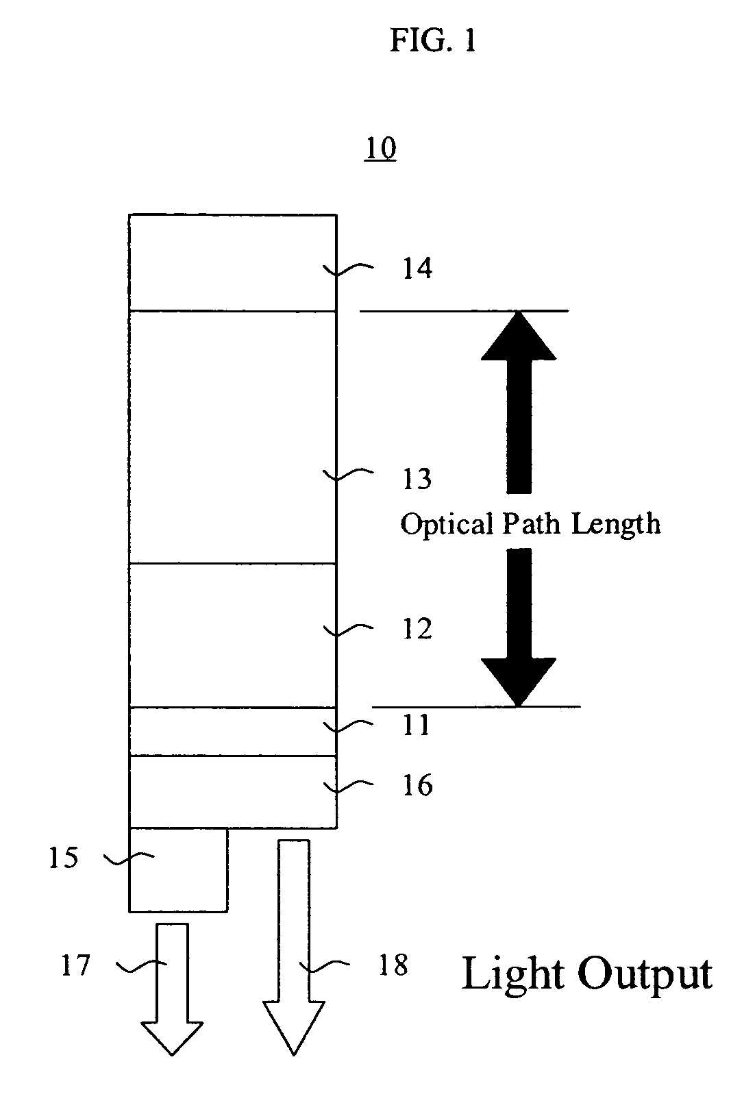
[0031] Three microcavity devices were prepared having a configuration as follows: a transparent glass substrate; a 20 nm Ag semi-transparent reflector; a 100 nm Al reflector; a plurality of organic layers with a refractive index of approximately 1.8; and no cavity spacer layer. In the first device, the total thickness of the organic layers was 296 nm. This thickness was selected so as produce a microcavity structure optimized to enhance emission in the red wavelengths. In the second device, the total thickness of the organic layers was 254 nm. This thickness was selected so as produce a microcavity structure optimized to enhance emission in the green wavelengths. In the third device, the total thickness of the organic layers was 219 nm. This thickness was selected so as produce a microcavity structure optimized to enhance emission in the blue wavelengths.

[0032]FIGS. 4A throu...


PUM


Abstract

An OLED device includes at least one light emitting layer arranged to produce light in a predetermined emitting area, a reflector and a semi-transparent reflector forming a microcavity structure for resonating the light produced in the at least one light emitting layer, and a color filter element disposed relative to a first portion of the predetermined emitting area so as to filter the light produced by the at least one light emitting layer and transmit substantially unfiltered light through a second portion of the predetermined emitting area.

Description

CROSS REFERENCE TO RELATED APPLICATIONS [0001] Reference is made to commonly assigned U.S. patent application Ser. No. 10 / 762,675 filed Jan. 22, 2004 by Dustin L. Winters, et al., entitled “Green Light-Emitting Microcavity OLED Device Using a Yellow Color Filter Element”; commonly assigned U.S. patent application Ser. No. 10 / 680,758 filed Oct. 7, 2003 by Yuan-Sheng Tyan, et al., entitled “White-Emitting Microcavity OLED Device”; commonly assigned U.S. patent application Ser. No. 10 / 346,424 filed Jan. 17, 2003 by Yuan-Sheng Tyan, et al., entitled “Microcavity OLED Devices”; commonly assigned U.S. patent application Ser. No. 10 / 356,271 filed Jan. 31, 2003 by Yuan-Sheng Tyan, et al., entitled “Color OLED Display With Improved Emission”; commonly assigned U.S. patent application Ser. No. 10 / 368,513 filed Feb. 18, 2003 by Yuan-Sheng Tyan, et al., entitled “Tuned Microcavity Color OLED Display”; and commonly assigned U.S. patent application Ser. No. 10 / 643,837 filed Aug. 19, 2003 by Dusti...

Claims


Application Information

Patent Timeline
IPC IPC(8): H01L51/50H05B33/12H01L51/52H01L27/32
CPCH01L27/3211H01L27/322H01L51/5036H01L51/5265H10K59/35H10K59/38H10K50/125H10K50/852
Inventor WINTERS, DUSTIN L.
Owner GLOBAL OLED TECH
Why Eureka
Try Eureka