Cooling of a data centre

a data center and cooling technology, applied in the field of cooling techniques, to achieve the effect of high availability and fault tolerance, minimizing the chance of unforeseen failure, and achieving energy efficiency

Inactive Publication Date: 2005-10-13
SCHNEIDER ELECTRIC IT CORP
View PDF56 Cites 417 Cited by
  • Summary
  • Abstract
  • Description
  • Claims
  • Application Information

AI Technical Summary

Benefits of technology

The invention is a containment system that can safely house any type of server, including blade servers, from any vendor or OEM. The system is designed to provide high availability and fault tolerance with minimum human intervention. The system architecture is also scalable, allowing users to adjust the level of secure provision based on their current needs. The system is designed to be energy efficient and takes into account variables such as room surface topography and equipment loads. The invention provides a pre-configured system that addresses interface problems between elements and allows users to meet their audit needs with ease.

Problems solved by technology

The technical problem addressed in this patent is how to effectively cool high-density computer equipment in a compact manner without compromising the reliability of individual components. Current cooling methods require significant amounts of unused space and lack efficient airflow movements. Additionally, conventional cooling solutions tend to have inflexible limitations regarding the addition of power and fail to address the challenge of scaling the size of the datacenter based on the amount of load needed.

Method used


Image

  • Cooling of a data centre
  • Cooling of a data centre
  • Cooling of a data centre

Examples


Embodiment Construction

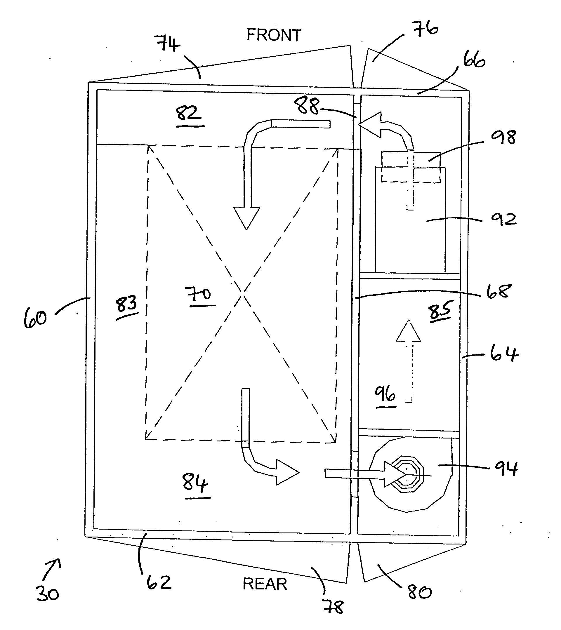
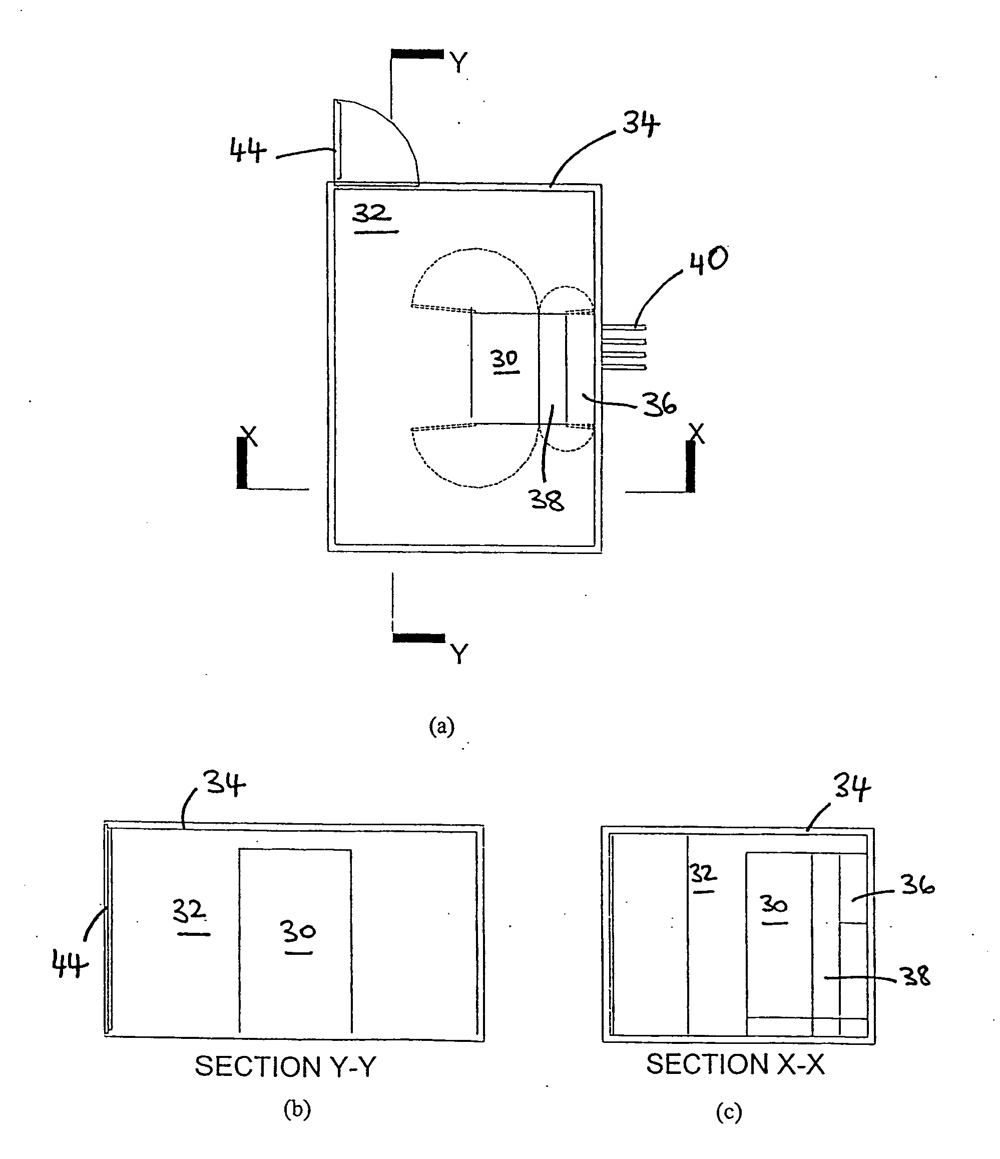
[0166] Referring firstly to FIGS. 2(a), 2(b) and 2(c), FIGS. 3(a), 3(b) and 3(c) and FIG. 4, preferred embodiments of the invention comprise three main elements which together enable an autonomous cabinet system 28, in the sense of a data center facility within a single equipment cabinet that does not rely on external service provision other than electrical power and coolant connections. If required, power and coolant facilities can be provided using plant skids which may, for example, include a generator set for the provision of electrical power. Suitably secure mains power connections are of course possible and, in most cases, preferred.

[0167] The first element of the system is the equipment cabinet 30 itself, which is sealed from its immediate environment. When used in non-controlled environments 32 as in FIGS. 2(a), 2(b) and 2(c), the cabinet is placed within a secondary outer enclosure 34 which insulates it from the environment and provides a zone where humidity can be control...


PUM


Abstract

A cabinet for housing a vertical array of heat-producing units has an equipment chamber adapted to support the array such that the array cooperates with the cabinet in use to define a first plenum, the first plenum having an inlet for receiving a flow of cooling fluid and an outlet defined by a plurality of openings through the array whereby the first plenum communicates with the openings in use to exhaust substantially all of the flow of cooling fluid through the openings and hence through the array, wherein the inlet to the first plenum admits fluid to the first plenum in a substantially horizontal direction. Related methods and data centre installations are also disclosed and claimed.

Description


Claims


Application Information

Patent Timeline
Owner SCHNEIDER ELECTRIC IT CORP
Why Eureka
Try Eureka