Fibre channel switching fabric port control

a fiber channel and fabric technology, applied in data switching networks, fault recovery arrangements, multiplex communication, etc., can solve the problems of difficult implementation of all these network switch features, common limiting factors of computer system performance, and unique problems of fibre channel fabrics

Inactive Publication Date: 2005-10-13
AVAGO TECH INT SALES PTE LTD
View PDF93 Cites 24 Cited by
  • Summary
  • Abstract
  • Description
  • Claims
  • Application Information

AI Technical Summary

Problems solved by technology

A common limiting factor in computer system performance is the path from the main central processing unit (CPU) to storage, or the I / O path.
Because of the high link speeds, Fibre Channel fabrics face unique problems that are not present in current network switch design.
All these network switch features are more difficult to implement when the incoming frame rate is high, as in the case of Fibre Channel.
There are no currently available microprocessors which can in real time route sixteen lines of incoming frames with a link speed of 1 gigabit per second.
Frame validation creates another set of problems.
Still the problem exists to determine the route for many simultaneous incoming frames at one gigabit per second.
Another problem with fabric realization is the support of the Arbitrated Loop topology.
Current fabric implementations do not support this topology.
Efficient support of both connection based classes of service (i.e., Class 1) and connectionless classes of service (i.e., Class 2 and 3) is also a challenge.
Coordination between the different switch cores can be a burdensome task.
This leads to inefficiencies, e.g., a connectionless switch core cannot switch Class 1 traffic if routes are not determined in frame time (i.e., less than one microsecond) and a connection switch core is very inefficient when routing Class 2 and Class 3 traffic.

Method used


Image

  • Fibre channel switching fabric port control
  • Fibre channel switching fabric port control
  • Fibre channel switching fabric port control

Examples


Embodiment Construction

[0066]

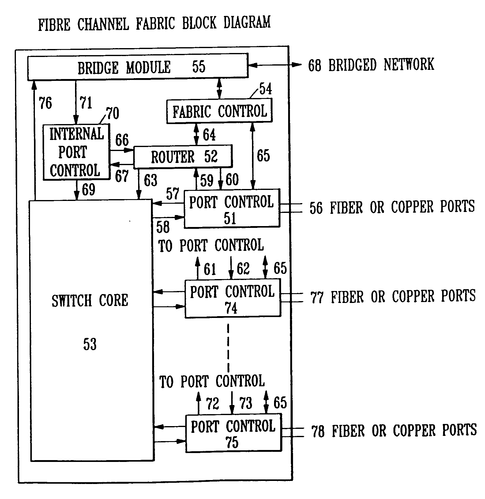
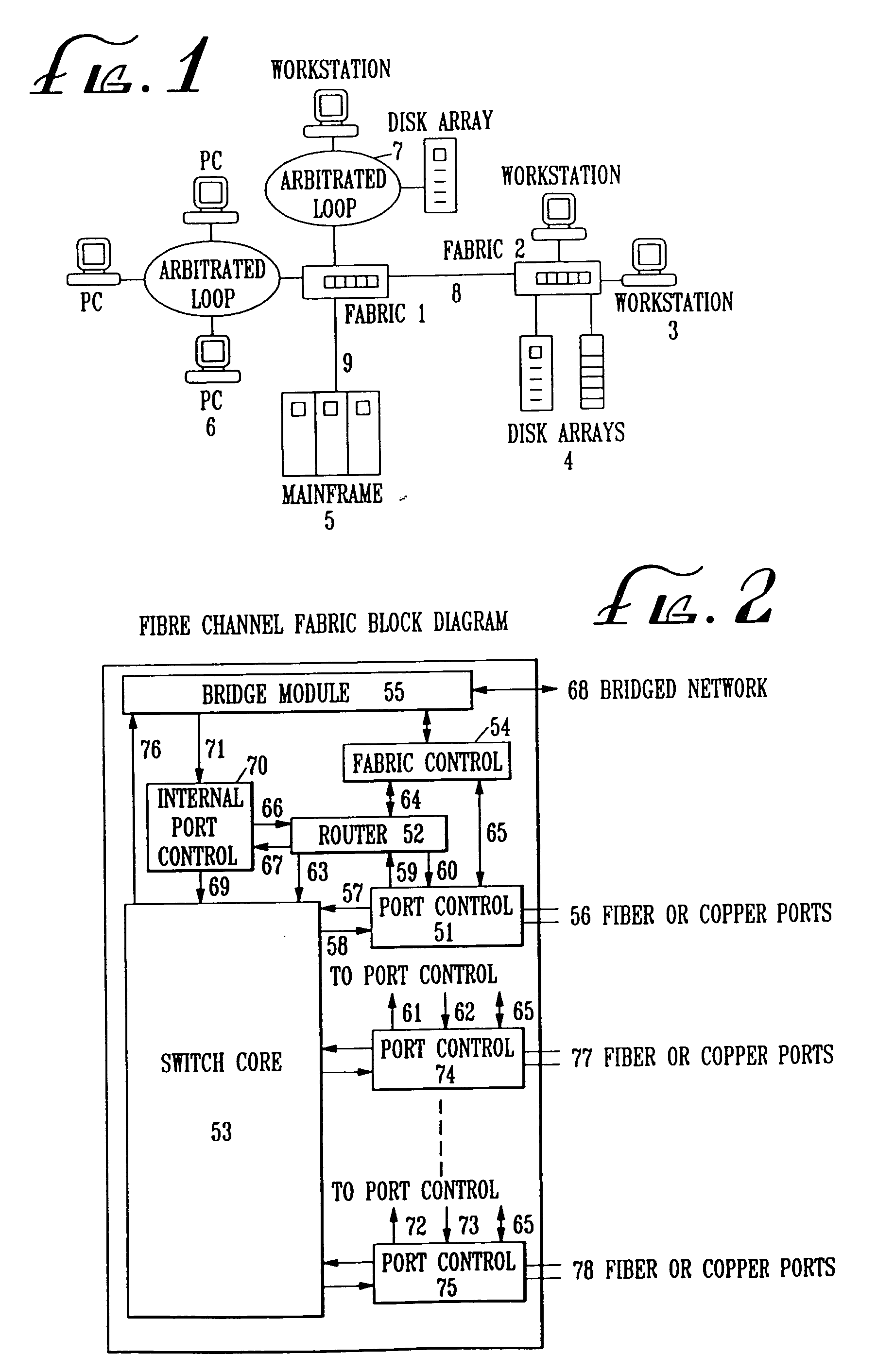
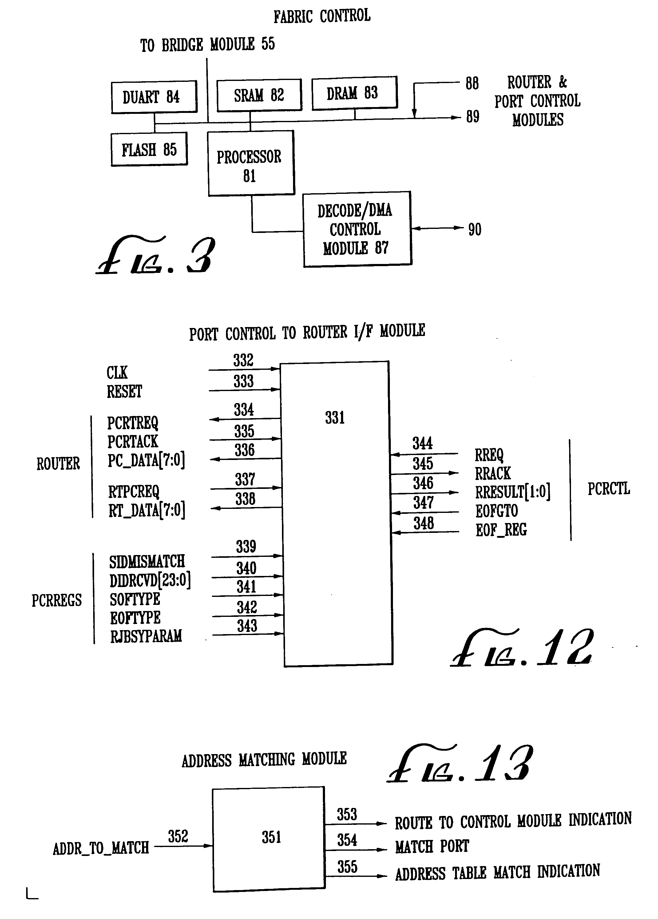
TABLE OF CONTENTSA.DefinitionsB.Fibre Channel Fabric ModelC.Fabric Control ModuleD.Fabric Router 1.Port Control Route Request Interface Module 2.Port Control Route Response Interface Module 3.Address Table 4.Address Match Module 5.Blocked Route Request Table 6.Blocked Route Request Port Register Array 7.Blocked Route Request Timer 8.Route Request Unblock Determination Module 9.Route Request Selector10.Route Determination Module11.Route State Table12.Router Statistics Gathering Module13.Router Control FSME.Port Control1.Port Control Module2.FIFO Overrun Prevention Logic3.Processor / Data Arbitration Logic4.Port Control Hub ModuleF.Switch CoreG.Router ModuleH.Other Documents

[0067] A. Definitions

[0068] For expository convenience, the present invention is referred to as the Fibre Channel Fabric or Fabric, the lexicon being devoid of a succinct descriptive name for a system of the type hereinafter described.

[0069] The “Fibre Channel ANSI standard” describes the physical interface, ...


PUM


Abstract

The Fibre Channel standard was created by the American National Standard for Information Systems (ANSI) X3T11 task group to define a serial I / O channel for interconnecting a number of heterogeneous peripheral devices to computer systems as well as interconnecting the computer systems themselves through optical fiber and copper media at gigabit speeds (i.e., one billion bits per second). Multiple protocols such as SCSI (Small Computer Serial Interface), IP (Internet Protocol), HIPPI, ATM (Asynchronous Transfer Mode) among others can concurrently utilize the same media when mapped over Fibre Channel. A Fibre Channel Fabric is an entity which transmits Fibre Channel frames between connected Node Ports. The Fibre Channel fabric routes the frames based on the destination address as well as other information embedded in the Fibre Channel frame header. Node Ports are attached to the Fibre Channel Fabric through links.

Description

RELATED APPLICATIONS [0001] This application is a continuation of U.S. application Ser. No. 09 / 330,398, issued on Jun. 7, 2005 as U.S. Pat. No. 6,904,053, entitled “Fibre Channel Switching Fabric”, which is a divisional of U.S. application Ser. No. 08 / 801,471, now issued as U.S. Pat. No. 6,185,203, entitled “Fibre Channel Switching Fabric”, and are incorporated herein by reference as if fully set forth herein.FIELD OF THE INVENTION [0002] The present invention relates to input / output channel and networking systems, and more particularly to a digital switch which switches Fibre Channel frames at link speeds of up to at least one gigabit per second (i.e., one billion bits per second). BACKGROUND OF THE INVENTION [0003] There is a never ending demand for increased computer system performance. A common limiting factor in computer system performance is the path from the main central processing unit (CPU) to storage, or the I / O path. The CPU usually requires data from attached storage man...

Claims


Application Information

Patent Timeline
Patent Type & Authority Applications(United States)
IPC IPC(8): H04L45/74H04J3/16H04L12/28H04L12/56H04L45/28H04L47/30H04L47/80H04L49/111
CPCH04L49/205H04L49/25H04L49/30H04L49/351H04L2012/5679H04L49/604H04B10/03H04L45/28H04L47/24H04L49/357H04L45/745H04Q11/0066H04Q2011/0052H04Q2011/0073H04L47/30H04L47/805
Inventor BERMAN, STUART B.
Owner AVAGO TECH INT SALES PTE LTD
Why Eureka
Try Eureka