Local transmission system for a vehicle

a transmission system and vehicle technology, applied in the direction of data switching network, instruments, synchronisation arrangement, etc., can solve the problems of data loss at the receiver, transmission from a transmitter station to a receiver station can get lost without being noticed by the transmitter station, and data loss can occur unnoticed at the receiver, so as to increase the reliability of transmission and simple and inexpensive hardware architecture

Inactive Publication Date: 2005-10-13
DAIMLER AG
View PDF5 Cites 19 Cited by
  • Summary
  • Abstract
  • Description
  • Claims
  • Application Information

AI Technical Summary

Benefits of technology

[0010] One object of the invention is to provide a local transmission system for a vehicle which transmits messages largely without losses, and can nevertheless can be equipped with simple and inexpensive hardware architecture.
[0011] This and other objects and advantages are achieved by the local transmission system according to the invention, in which a receiver station also acknowledges the reception of a last transmitted message of a data block, by means of a corresponding acknowledgement message sent to a transmitter station. In addition, before sending one of the messages, the transmitter station calculates an adjustable delay period and sends each of the messages to the receiver station only after the calculated delay period has elapsed. Acknowledgement of the reception of the last transmitted message of a data block advantageously ensures that none of

Problems solved by technology

However, one disadvantage of this transmission protocol is that messages transmitted from a transmitter station to a receiver station can get lost without being noticed by the transmitter station.
A loss can occur, for example, if a message arrives at the receiver within i

Method used


Image

  • Local transmission system for a vehicle
  • Local transmission system for a vehicle
  • Local transmission system for a vehicle

Examples


Embodiment Construction

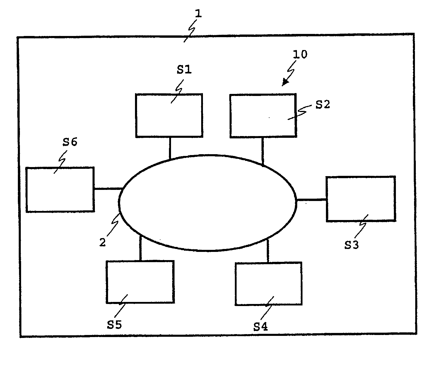
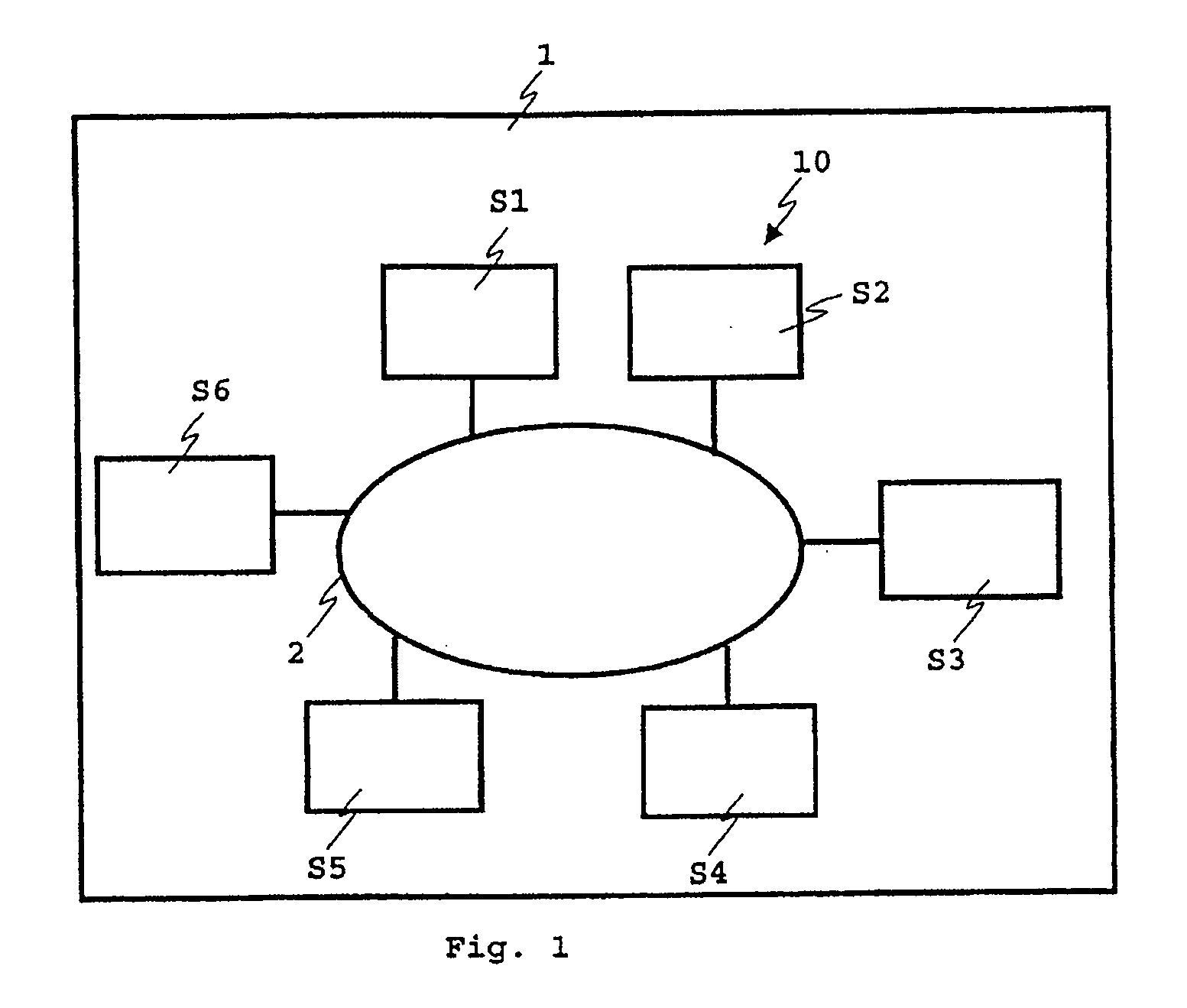
[0024] As can be seen from FIG. 1, a local transmission system 10 in a vehicle 1 comprises a number of stations S1 to S6, which are connected to one another for exchanging messages via a databus 2 (for example, a CAN databus, or an optical D2B or MOST databus). The stations S1 to S6 can act as transmitter station SS and / or as receiver station ES.

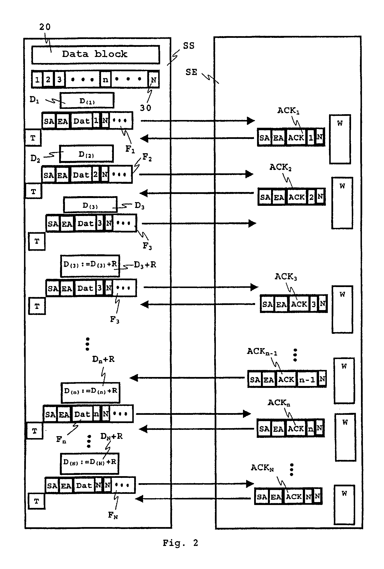
[0025] To explain the operation of the local transmission system, FIG. 2 shows by way of example a station acting as transmitter station SS and a station acting as receiver station ES of the transmission system 10. As can be seen from FIG. 2, a data block 20 to be transmitted is divided in the transmitter station SS into N data fragments 30 (with a predetermined size of, for example 48 bytes) which are in each case successively transmitted as part of a message F1 to FN to the receiver station ES. The receiver station ES acknowledges the reception of all messages F1 to FN transmitted by the transmitting station SS in each case individually b...


PUM


Abstract

A local transmission system for a vehicle comprises a number of stations which are connected to one another for exchanging messages via a databus, each message exhibiting a message frame with a predetermined structure. A data block to be transmitted is divided into N data packets which are successively transmitted as messages to the at least one receiver station, which individually acknowledges the reception of each of the messages, including the last such message of a data block, by sending an acknowledgement message. The transmitter station transmits a next successive message only if the acknowledgement message for the previous message has been received. Before sending each message, the transmitter station calculates an adjustable delay period, and only transmits such message only after the calculated delay period has elapsed.

Description

BACKGROUND AND SUMMARY OF THE INVENTION [0001] This application claims the priority of German patent document 10 2004 014 624.1, filed Mar. 25, 2004, the disclosure of which is expressly incorporated by reference herein. [0002] The invention relates to a local transmission system for vehicles, such as aircraft, ships, trains or motor vehicles. [0003] Such a local transmission system comprises a number of stations which are connected to one another for exchanging messages via a databus, such as a CAN databus, an optical D2B or a MOST databus. The individual stations are able to act as transmitter stations and / or as receiver stations. For transmission, each message exhibits a message frame with a structure that is dependent on the transmission protocol used. Depending on the application, various known protocols can be used for message transmission (for example, D2B or MOST protocols). Thus, in the case of a MOST databus, for example, a MAMAC protocol MOST Asynchronous Medium Access Co...

Claims


Application Information

Patent Timeline
IPC IPC(8): H04L12/56G01R31/08G06F11/00G08C15/00H04B7/216H04B7/26H04J1/16H04J3/14H04J3/24H04L1/00H04L1/16H04L1/18H04L12/26H04L12/40H04W28/00H04W56/00
CPCH04L1/16H04L2001/0094H04L1/188H04L1/1803
Inventor HRYCAJ, MICHAEL JORDANKUEBLER, FRIEDRICH
Owner DAIMLER AG
Why Eureka
Try Eureka