
Image forming device, powder feeding device, toner storage container, powder storage container, and method of recycling the containers

a technology of image forming and powder, which is applied in the field of image forming apparatus, toner storage containers, powder containers, etc., can solve the problems of deteriorating toner quality, affecting the righting moment of sponges, and inability to raise toner at acute angles

Active Publication Date: 2005-10-13
RICOH KK
View PDF13 Cites 100 Cited by
  • Summary
  • Abstract
  • Description
  • Claims
  • Application Information

AI Technical Summary

Benefits of technology

[0033] According to the present invention, since the toner container is dropped from above and supported by the opening-closing folder in the setting unit, setting of the toner container can be facilitated.
[0149] According to the present invention, a refill toner cartridge can be provided, in which toner leakage from the draining port at the time of detachment is suppressed, by storing the refill toner to be used in the image forming apparatus such as a copier, when the toner in the toner storage has been exhausted at least once, and guiding the refill toner from the toner storage to the draining port through the drain passage.

Problems solved by technology

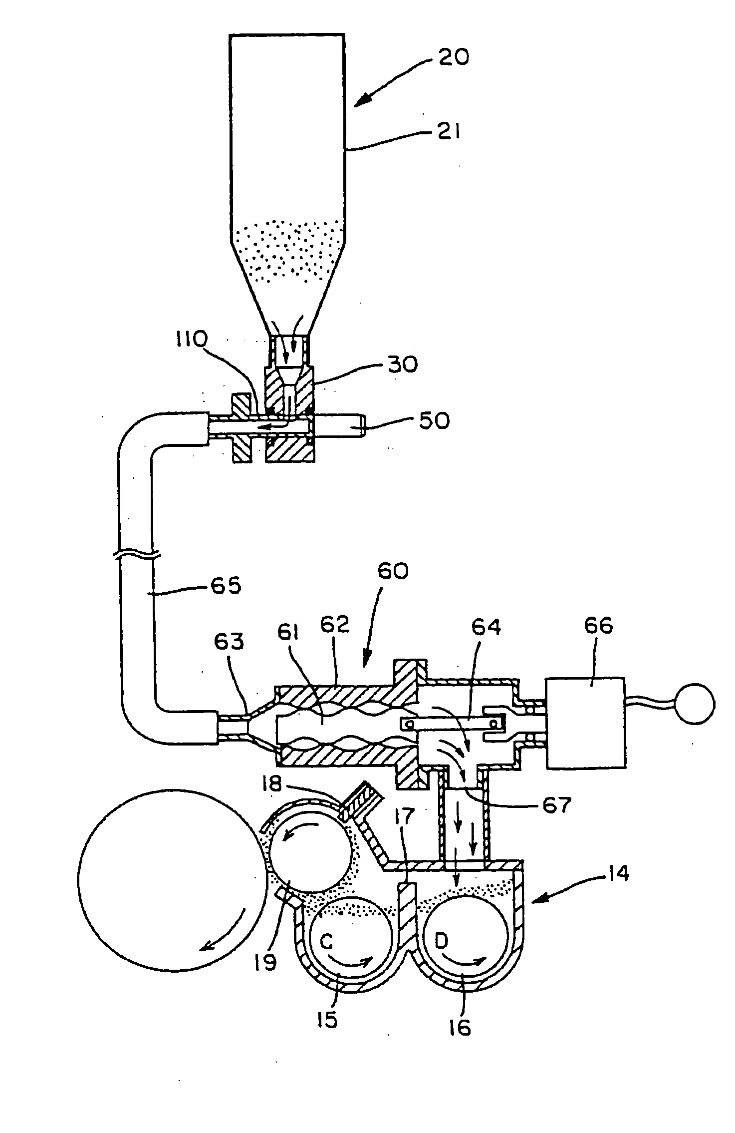
The toner transfer by the auger unit can control the transfer amount of the toner, but the transfer route is substantially limited to a linear route, and when the transfer route is long, coagulation of the toner may occur, thereby deteriorating the toner quality.
Further, with the auger unit, even if the transfer distance is short, the toner cannot be raised at an acute angle.
However, in the self-closing valve, the righting moment of the sponge may decrease due to curing at a low temperature, or due to a creep deformation with the lapse of time.
When the righting moment decreases, the toner may leak and scatter until the slit of the self-closing valve closes, at the time of taking out the toner container.
As a result, the supply amount of the toner becomes unstable, and hence the residual amount of toner in the toner container may increase extremely.
When a gap is generated, in the conventional configuration in which the toner draining unit is facing the direction of gravity of the toner container, the toner may leak from the gap, drop and scatter.
There is the possibility that the toner in the toner container leaks and scatters from this gap.
Therefore, at the time of recycling the parts of the toner container, a complicated work for detaching the sealing material formed of the elastic material, bonded to the body portion of the toner draining member (cap member) becomes necessary, causing a problem in that recycling of the toner container is not easy.
This problem occurs likewise when a powder container for storing powder other than the toner is used.

Method used


Image

  • Image forming device, powder feeding device, toner storage container, powder storage container, and method of recycling the containers
  • Image forming device, powder feeding device, toner storage container, powder storage container, and method of recycling the containers
  • Image forming device, powder feeding device, toner storage container, powder storage container, and method of recycling the containers

Examples


first embodiment

[0174] The present invention will be explained in further detail with reference to the accompanying drawings.

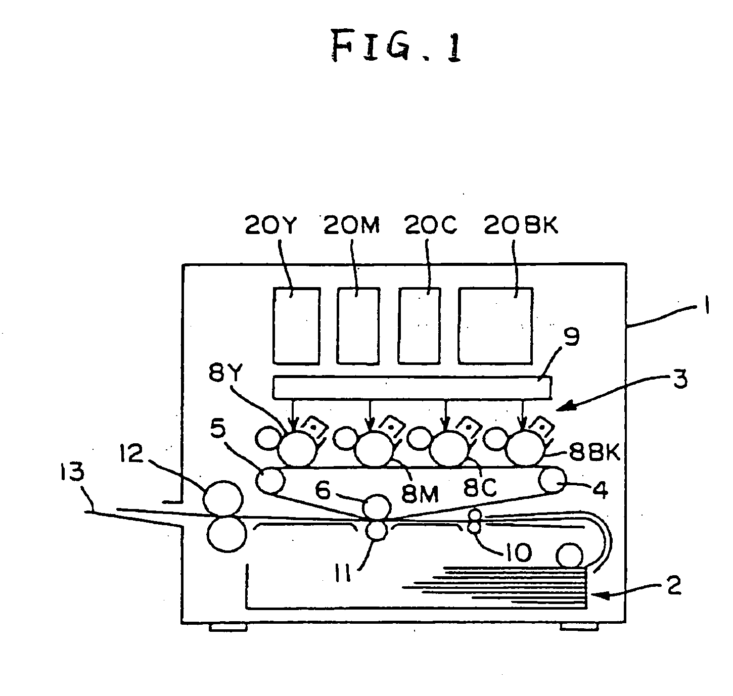
[0175]FIG. 1 is a schematic diagram of a color laser printer, being one example of an image forming apparatus according to the present invention. The color laser printer has a configuration such that an image forming unit 3 is arranged substantially at the center of an apparatus body 1, and a paper feeder 2 is arranged below the image forming unit 3. In the image forming unit, an intermediate transfer belt 7 is provided as an image carrier formed of an endless belt having flexibility and spanned over a plurality of rollers 4, 5, and 6. In the traveling side of the upper intermediate transfer belt 7 between the rollers 4 and 5, image forming units 8Y, 8C, 8M, and 8BK as four image forming units are arranged opposite to the intermediate transfer belt 7.

[0176] The four image forming units 8 respectively include a photosensitive drum as a latent image carrier abutting against t...

second embodiment

[0227] A second embodiment according to the present invention will be explained below.

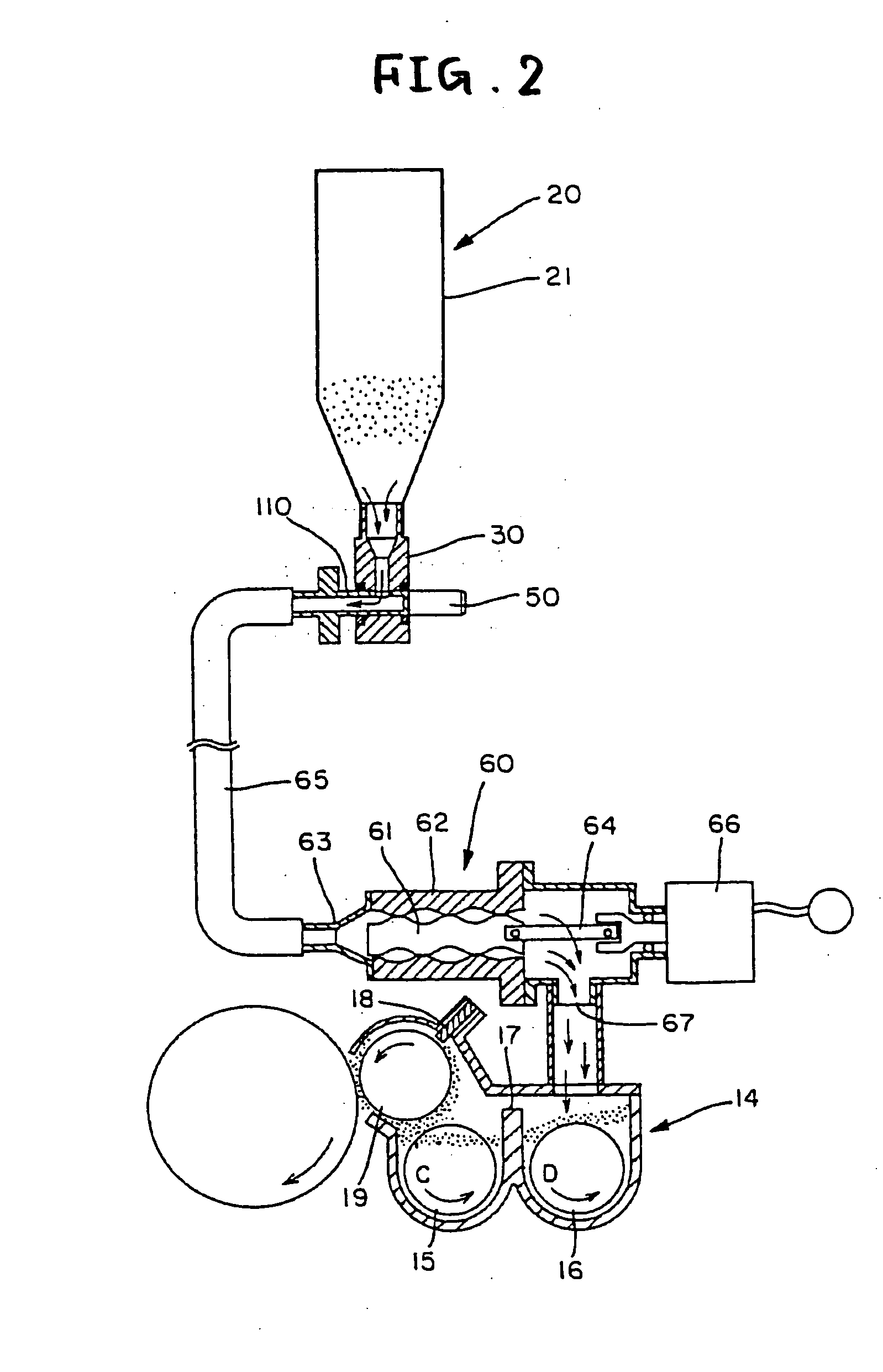
[0228] An example of the image forming apparatus (color laser printer) according to the second embodiment is similar to that shown in FIG. 1. Further, the toner supply container, the toner supplying apparatus, and the setting unit are the same as those shown in FIGS. 2 to 19. Therefore, repeated explanation is omitted, and only a characteristic point of the second embodiment will be explained herein.

[0229] As shown in FIG. 2, a bag-like container 21 as the toner container 20 is formed of a sheet material, being the flexible material, and hence has flexibility. The bag-like container 21 includes, as shown in FIG. 3, two sheets 21a and 21b constituting front and back surfaces, two sheets 21c and 21d constituting left and right sides, and an upper surface sheet 21e, and is formed by fusing these sheets. In the sheets 21c and 21d on the left and right sides, a fold 22 for folding inward of the contai...

third embodiment

[0264] A third embodiment according to the present invention will be explained below.

[0265] An example of the image forming apparatus (color laser printer) according to the third embodiment is similar to that shown in FIG. 1. Further, the toner supply container, the toner supplying apparatus, and the setting unit are the same as those shown in FIGS. 2 to 19. Therefore, repeated explanation is omitted, and only a characteristic point of the third embodiment will be explained herein.

[0266] When the axial length of the shutter member 50 is longer than the width between the front and back surfaces of the cap member 30, that is, the width Wb of the side, the shutter member 50 inserted into the shutter hole 41 protrudes from the cap member 30, and obstructs the installation of the container. Therefore, it is preferable that the length of the shutter member 50 be equal to the width Wb.

[0267] In the configuration of the present embodiment, the toner draining port 41a has an inner hole 33...


PUM


Abstract

A part of a toner supply path is formed in a setting unit, and a nozzle coupled to a toner container is provided, wherein the fitting direction of the toner container to the setting unit and the coupling direction of the nozzle to the toner container are different.

Description

TECHNICAL FIELD [0001] The present invention relates to an image forming apparatus, a powder supplying unit, a toner container, a powder container, and a reproduction a method of recycling the powder container, and more particularly, to an apparatus that stores a powder such as toner used for the image forming apparatus and reliably supplies the powder to the apparatus body, a container, and a method of recycling the powder container. BACKGROUND ART [0002] In a conventional forming apparatus, for example, with a two-component developing unit in which the developing unit that visualizes an electrostatic latent image formed on, for example, an image carrier, uses a toner including a toner and a carrier, since the toner is consumed with the formation of an image, it is necessary to sequentially supply the toner by the consumed amount. Therefore, in the image forming apparatus, a toner container storing the toner is provided, to supply the toner by the consumed amount from the container...

Claims


Application Information

Patent Timeline
IPC IPC(8): G03G15/08
CPCG03G2215/0682Y10S222/01G03G15/0874G03G15/0877G03G15/0894G03G15/0865G03G15/0855G03G15/0886
Inventor KATSUYAMA, GOROIWATA, NOBUOKASAHARA, NOBUOMURAMATSU, SATOSHIMATSUMOTO, JUNICHI
Owner RICOH KK
Learn More