
Durable fill block for flow of fluids through a hinged lid

a fill block and lid technology, applied in the field of chambers with hinged lids, can solve the problems of affecting the durability of the fill block, the damage to the insert sheet and the instruments, and the potential damage to the chamber interior, etc., and achieve the effect of greater durability

Inactive Publication Date: 2005-10-13
STERIQUIP
View PDF10 Cites 6 Cited by
  • Summary
  • Abstract
  • Description
  • Claims
  • Application Information

AI Technical Summary

Benefits of technology

[0006] Accordingly, it is an object of the present invention to provide a hinged lid assembly having greater durability.
[0007] It is another object of the present invention to provide a fill block connected to a hinged lid that is more efficient at permitting fluid to escape and flow through a system covered by the lid and that did not cause damage to surrounding structures that it touches or is in proximity to during opening and closing.
[0008] Another object of the invention is to provide a lid assembly that is more durable and less subject to damage or breaking.
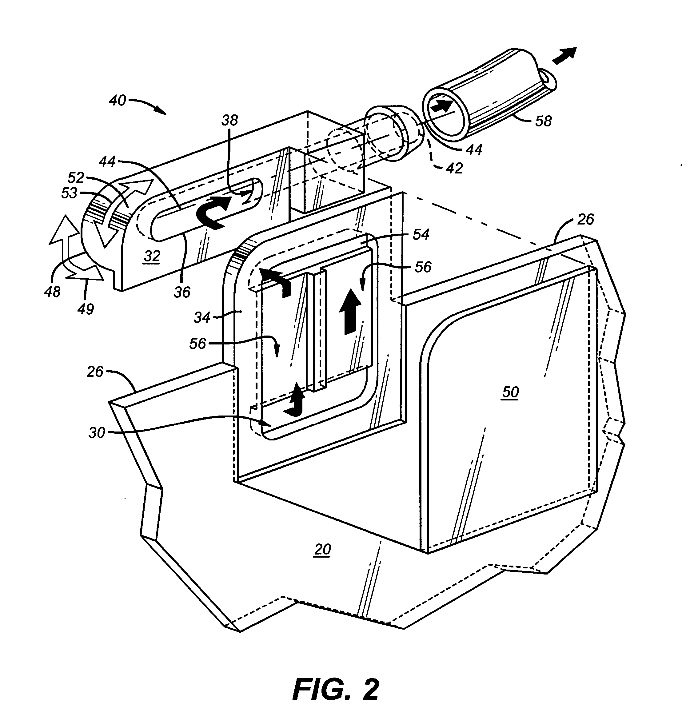
[0009] In carrying out these and other objects of the invention, there is provided, in one form, a fill block for transport of fluid through a hinged lid. The fill block has a block body; a substantially flat contact face adapted to connect with an insert sheet; a fluid pathway having a first aperture on the flat contact face and a second aperture on a different portion of the block body than the flat contact face. The fill block also has at least one rounded surface to minimize impact with a structure when the insert sheet is closed or opened, where the insert sheet is connected to, integral with or the same thing as the hinged lid.

Problems solved by technology

Experience has shown that frequent and constant opening and closing of the lid not only stresses and damages these blocks and conduits, but has the potential of damaging the chamber interior, processing tray and / or structures of the system near the hinge.
Additionally, if an operator is not careful, the scopes and other instruments placed in the chamber for sterilizing may not be properly aligned or oriented and may extend into the space that the insert sheet normally occupies at the time the lid is closed resulting in damage both to the insert sheet and the instruments.

Method used


Image

  • Durable fill block for flow of fluids through a hinged lid
  • Durable fill block for flow of fluids through a hinged lid
  • Durable fill block for flow of fluids through a hinged lid

Examples


Embodiment Construction

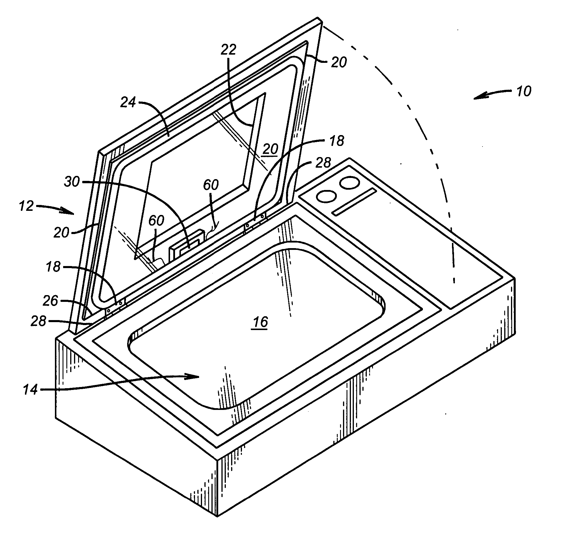
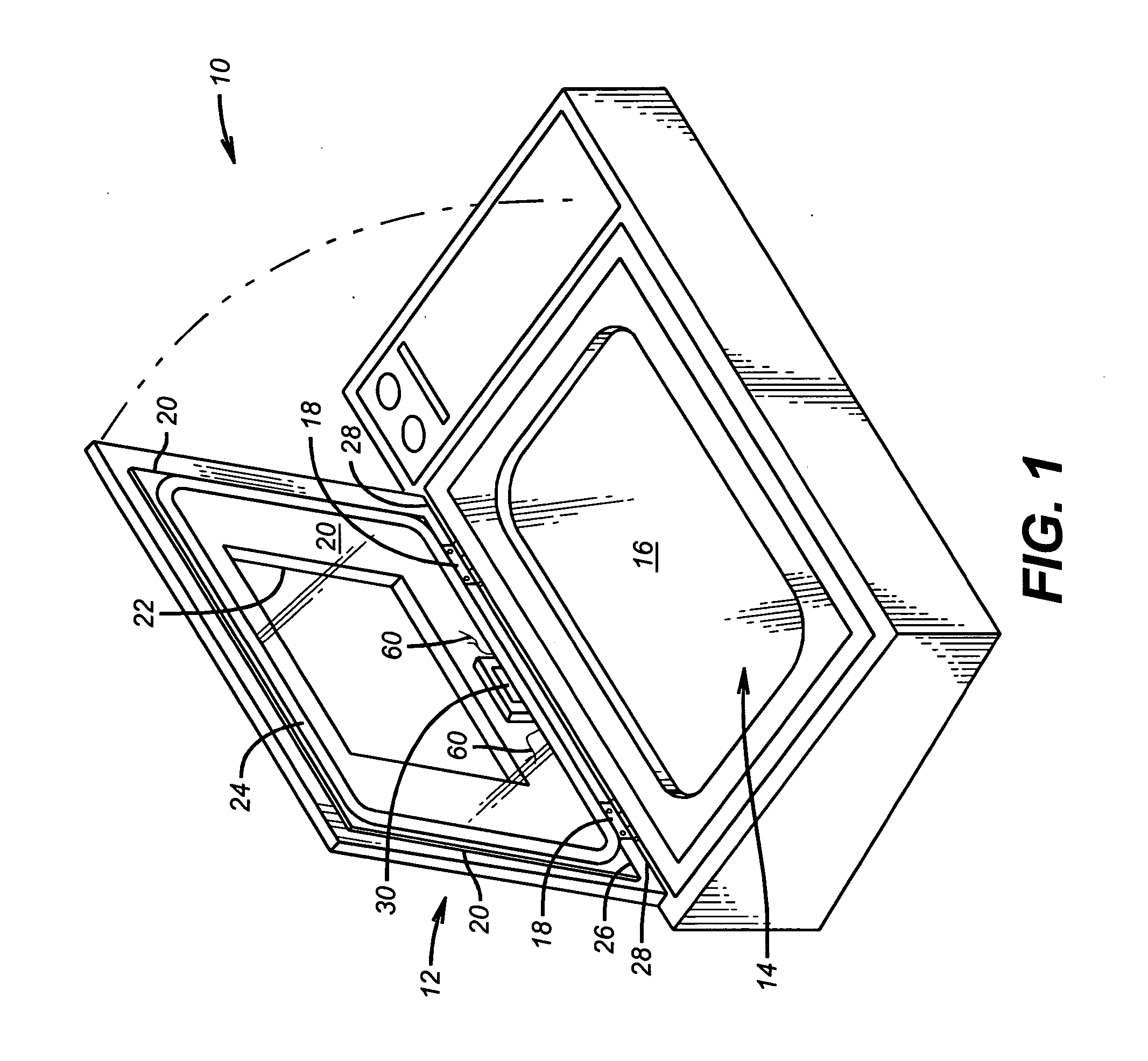
[0019] Shown in FIG. 1 is one non-limiting embodiment of a sterilizing system or device 10 having a hinged lid 12 and an interior chamber 14. The interior chamber 14 may include, but is not necessarily limited to, a processing tray 16 shown in this particular embodiment, but also a structure integral with device 10, a gasket, a spacer, a cover, a handle, a frame, and other like structures.

[0020] In the particular embodiment shown in FIG. 1, the hinged lid 12 is in the open position bearing on hinges 18. The number of hinges 18 is not important so far as hinged lid 12 pivots or swings on at least one hinge 18. Lid 12 has an insert sheet 20 within it. Insert sheet 20 may be connected to, integral with or the same thing as hinged lid 12 in various non-limiting embodiments. Insert sheet 20 may be transparent and lid 12 may have a window 22 therein to permit viewing of anything within chamber 14, as in the FIG. 1 embodiment. Lid 12 may also have a gasket 24 for forming a seal with the c...


PUM

PropertyMeasurementUnit
weightaaaaaaaaaa
heightaaaaaaaaaa
depthaaaaaaaaaa

Abstract

A fill block for injection of fluid through a hinged lid is improved by making the fluid pathway therethrough of a constant cross-sectional area, and by providing one or more rounded surfaces to reduce or eliminate impact and contact with surrounding structures when the lid is open and closed. Using a more durable and flexible material for the fill block and insert sheet increases the lifetime of both components and reduces or eliminates the tendency of these components to stress crack. Polycarbonate is one example of such durable and flexible material.

Description

CROSS-REFERENCE TO RELATED APPLICATION [0001] This application claims the benefit of U.S. provisional application No. 60 / 559,470 filed Apr. 5, 2004.FIELD OF THE INVENTION [0002] The present invention relates to methods and apparatus for allowing air to escape from a chamber having a hinged lid and allowing liquids introduced to the chamber to flow to a float switch indicating a full chamber, and more particularly relates, in one embodiment, to methods and apparatus for allowing air and liquids flow to and from a chamber having a hinged lid, where the flow of air and liquids is through the lid near the hinge. BACKGROUND OF THE INVENTION [0003] Apparatus are known for having hinged lids that open to permit access to a chamber in the apparatus behind the lid. One example of such an apparatus is a sterilizing system where various objects such as immersible surgical and diagnostic devices, e.g. medical scopes and instruments are inserted to sterilize them. Generally, the lid is opened to...

Claims


Application Information

Patent Timeline
Patent Type & Authority Applications(United States)
IPC IPC(8): A61L2/00A61L2/18A61L2/26
CPCA61L2/186A61L2202/24A61L2/26A61L2/208
Inventor DRUMMOND, JOHN A.MARTINEZ, ROBERT R.
Owner STERIQUIP
Learn More