
Sector switching detection method

a sector switch and detection method technology, applied in the field of wireless communication systems, can solve the problems of increasing the complexity of algorithms, unrealistic solutions for improving the reliability of switch detection, and introducing a great deal of processing delay, so as to achieve reliable and accurate detecting of sector switch indications, and keep the level of acceptance low

Active Publication Date: 2005-10-13
RPX CORP +1
View PDF7 Cites 20 Cited by
  • Summary
  • Abstract
  • Description
  • Claims
  • Application Information

AI Technical Summary

Benefits of technology

[0010] The present invention is directed to a method for reliably and accurately detecting a sector switch indication from a mobile device. A set of active sectors, which correspond to sectors that may be chosen by the mobile device as a new serving sector, monitors the mobile device for the sector switch indication. The sector switch indication includes the identity of the base station / sector having the strongest communication link with the mobile device. Once the sector switch indication is made for a predetermined period of time, the mobile device links with the identified sector to make that sector the serving sector.
[0011] In one embodiment, the method incorporates an algorithm having two switch detection processes that run concurrently and independently with a sector switch detection block at each of the active set sectors. A frame-based switch detection process operates over a given period, while a sliding window-based detection system operates over a selected multiple of periods. The frame-based switch detection process is used to predict the actual time of the sector switch. The sliding window-based switch detection process is used to reliably determine the switch indication, with low miss and false alarm probabilities, in at least one active sector (e.g., the sector with the strongest link to the mobile device) while ensuring that false alarm reports from all active sectors, especially those with weak links to the mobile device, are kept at acceptably low levels.

Problems solved by technology

This introduces a great deal of processing delay.
Moreover, the limited bandwidth between the base stations and the central entity as well as the limited processing power at the central entity itself makes more complex algorithms an unrealistic solution for improving switch detection reliability.

Method used


Image

  • Sector switching detection method
  • Sector switching detection method
  • Sector switching detection method

Examples


Embodiment Construction

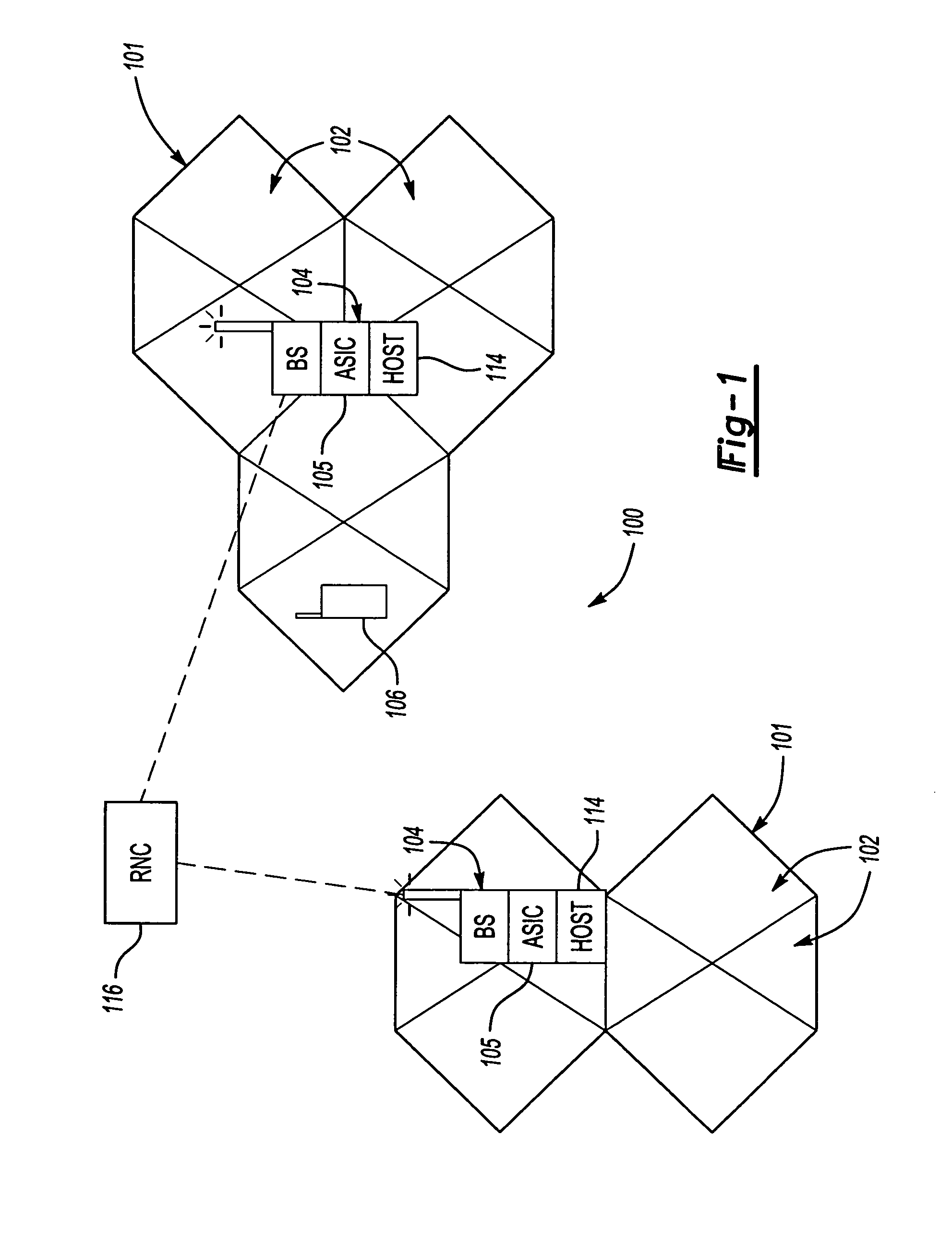
[0017]FIG. 1 is an illustrative example of the wireless communication system 100 in which the inventive method can be executed. As explained above, the system 100 is divided into cells 101 having multiple sectors 102 corresponding with different geographic areas, with each base station 104 being associated with one or more sectors 102. The base station 104 and the mobile device 106 can distinguish among the sectors 102 via any known metric implemented by, for example, a baseband processing application specific integrated circuit (ASIC) 105 in the base station 104. For example, each sector 102 may be associated with a particular Walsh symbol (also called a “Walsh cover”), which would be used by the base station 104 and the mobile device 106 to identify each sector 102.

[0018] The system 100 may also include at least one central entity that can handle data corresponding to multiple sectors 102 and / or multiple base stations 104. The central entity may be, for example, a host processor ...


PUM


Abstract

A sector switch detection method incorporates two independent, concurrent switch detection processes within a sector switch detection block. A frame-based switch detection process operates over a given single period, while a sliding window-based detection system operates over a selected multiple of periods.

Description

BACKGROUND OF THE INVENTION [0001] 1. Field of the Invention [0002] This invention relates to wireless communication systems. [0003] 2. Description of the Related Art [0004] Communication systems, such as wireless systems, are designed to meet various subscriber demands. Service providers continuously seek ways to improve the overall performance of the communication system. In the past, wireless communication systems have been used for voice communications, but more recent technological developments have allowed high speed data transmission as well. As wireless communications become more and more popular for subscribers to obtain data (i.e., e-mail or information from the internet), communication systems should be capable of a higher throughput and be tightly controlled to maintain a high quality of service. Communication is conducted according to any desired communications standard, such as the Universal Mobile Telecommunications Standard (UMTS) or a CDMA standard. [0005] As is kno...

Claims


Application Information

Patent Timeline
Patent Type & Authority Applications(United States)
IPC IPC(8): H04L12/56H04W24/00H04W36/00H04W36/06H04W36/30
CPCH04W36/0083H04W36/30H04W36/06H04W36/302A47B97/001B43L1/04G09F15/00G06F3/042G06F3/043G06F3/03545A47B2220/0022
Inventor KONG, HONGWEIVASUDEVAN, SUBRAMANIANYE, HENRY HUIZOU, JIALIN
Owner RPX CORP
Learn More