Gas distribution device
- Summary
- Abstract
- Description
- Claims
- Application Information
AI Technical Summary
Benefits of technology
Problems solved by technology
Method used
Image

Examples
Embodiment Construction
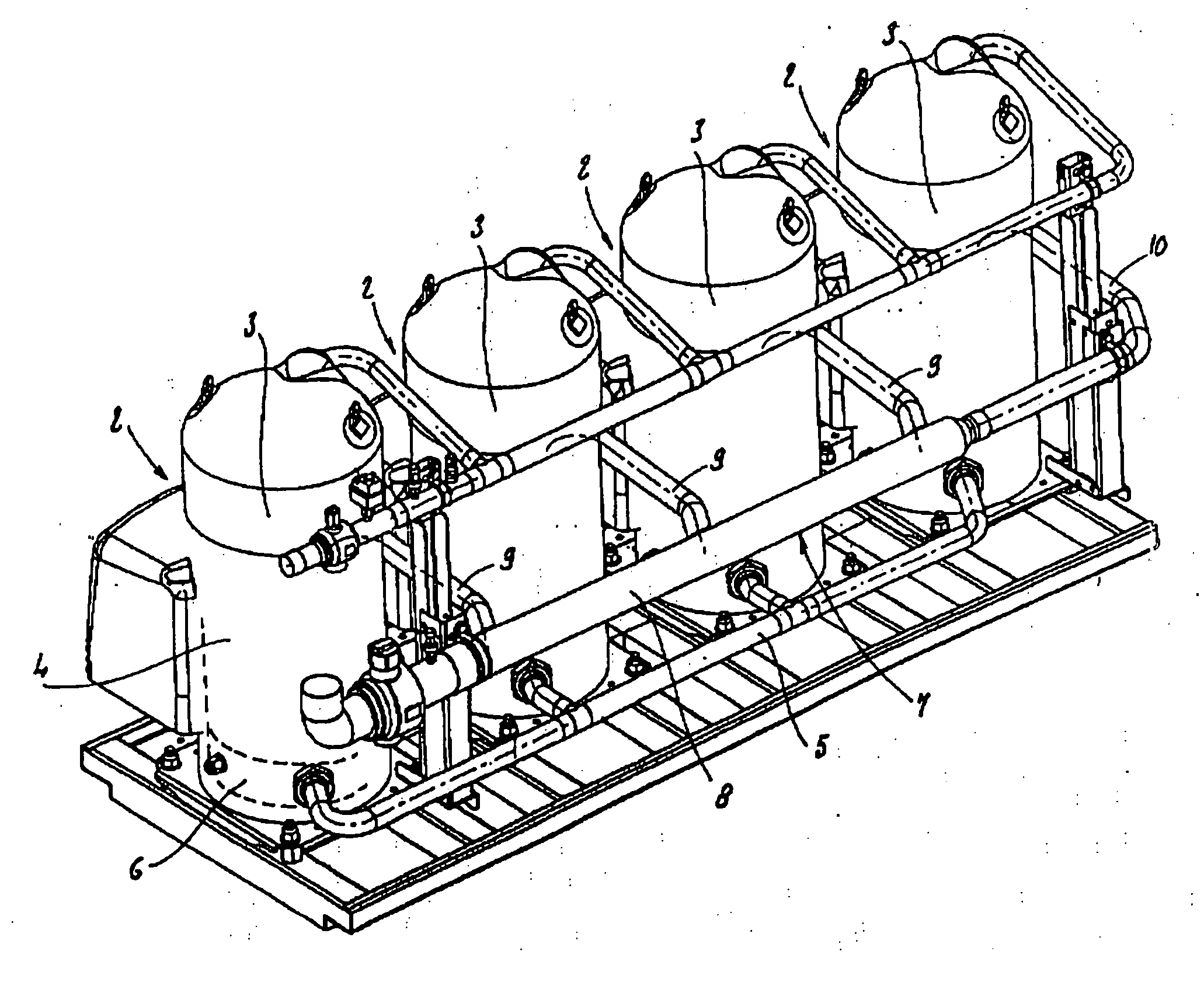
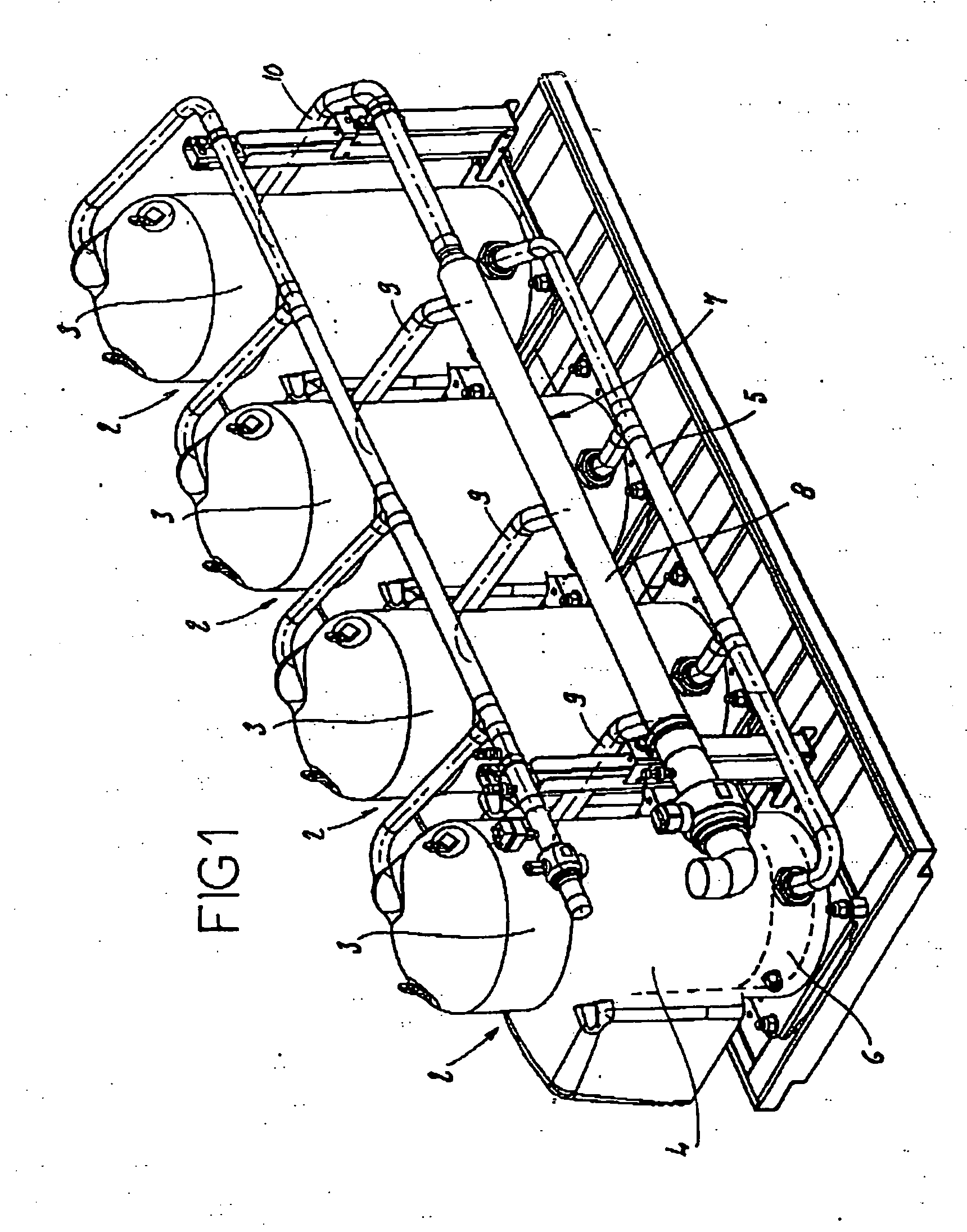
[0038]FIG. 1 describes an arrangement of compressors in parallel, including: [0039] four refrigeration compressors, each having a body 3 delimiting an inside space 4; [0040] an oil level equalization tube 5 providing communication between the oil pans 6 provided in the body 3 of compressors 2; and [0041] a suction gas distribution device 7 comprising a substantially straight distribution tube 8 as well as branch tubes 9, 10 providing communication between the distribution tube 8 and the inside spaces 4 of the bodies of compressors 2.
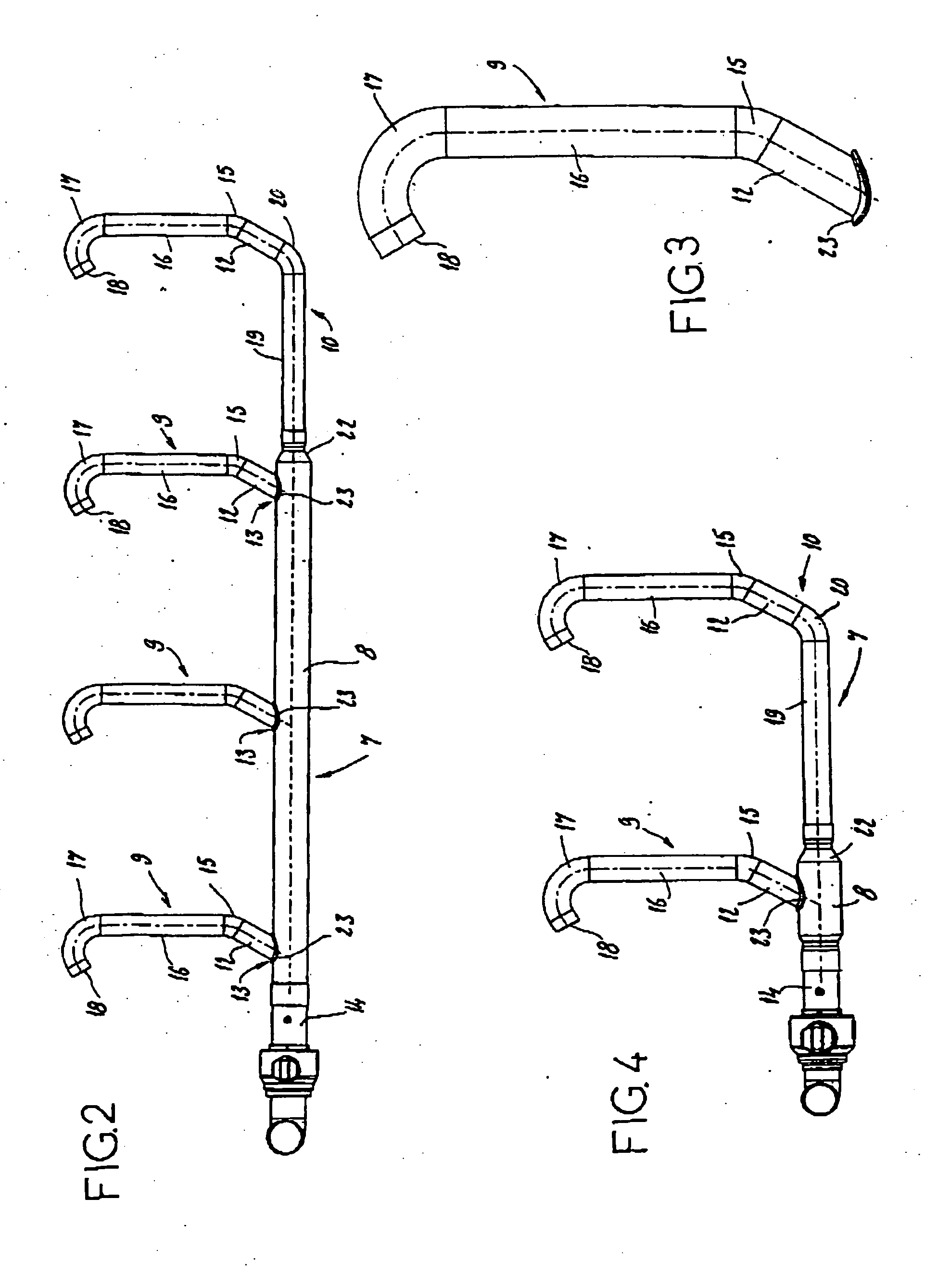
[0042]FIG. 2 shows the distribution device 7 according to a first embodiment for an arrangement of four compressors. The distribution tube 8 has, upstream of the first branch 13, a straight portion 14 that is about 330 mm long and has five to seven times the outside diameter of the distribution tube 8. In this embodiment, the outside diameter of the branch tubes 9 is essentially equal to 1 5 / 8 inches (one inch being equal to 2.540 cm), the outside diame...
PUM
 Abstract
Description
Claims
Application Information
 - R&D
- Intellectual Property
- Life Sciences
- Materials
- Tech Scout
- Unparalleled Data Quality
- Higher Quality Content
- 60% Fewer Hallucinations
Browse by: Latest US Patents, China's latest patents, Technical Efficacy Thesaurus, Application Domain, Technology Topic, Popular Technical Reports.
© 2025 PatSnap. All rights reserved.Legal|Privacy policy|Modern Slavery Act Transparency Statement|Sitemap|About US| Contact US: help@patsnap.com