

Baffle for an automotive vehicle and method of use therefor
a technology for automotive vehicles and baffles, applied in the direction of roofs, manufacturing tools, transportation and packaging, etc., can solve the problems of increasing the difficulty of assembling baffles to the vehicles, creating cavities that are difficult to seal, and reducing the efficiency of automotive vehicle interior passenger compartments
- Summary
- Abstract
- Description
- Claims
- Application Information
AI Technical Summary
Benefits of technology
Problems solved by technology
Method used
Image

Examples
Embodiment Construction
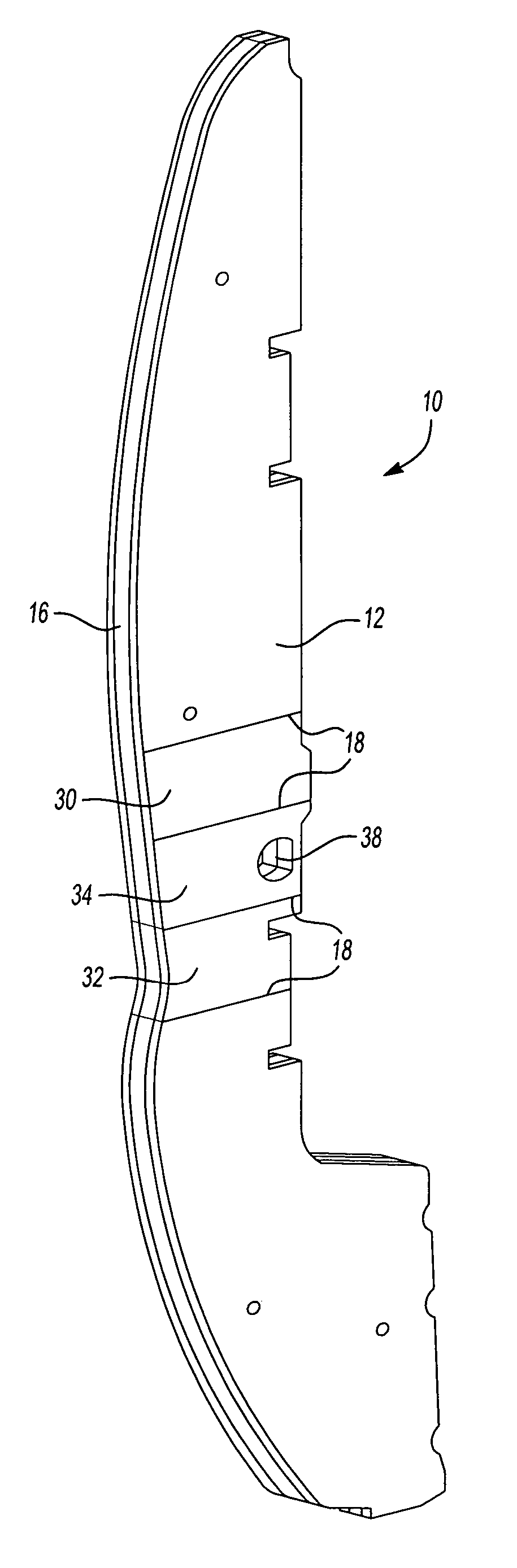
[0014] The present invention is predicated upon providing an improved system for sealing and baffling a cavity of an automotive vehicle. The baffle typically includes one or more of the following: [0015] 1) at least one, but preferably a pair of carrier members (e.g., carrier layers); and [0016] 2) a layer of expandable material at least partially disposed upon the one or more carrier members.
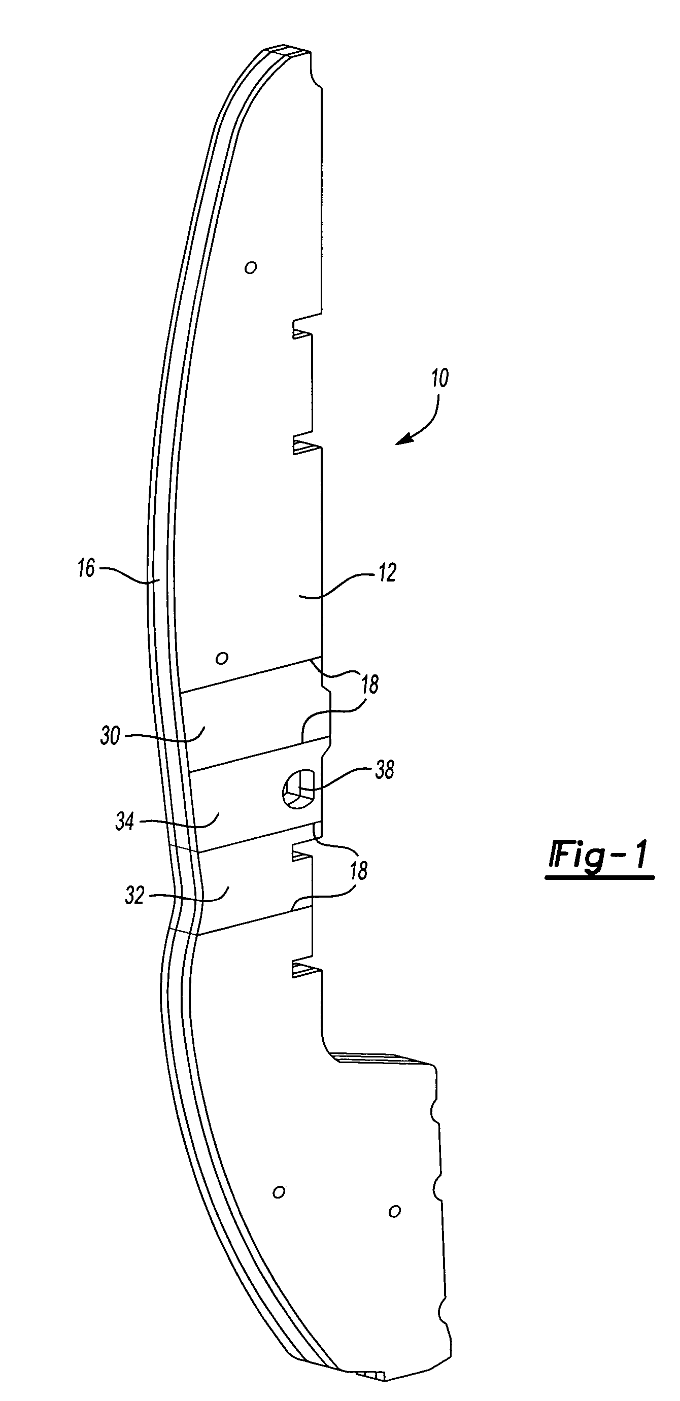
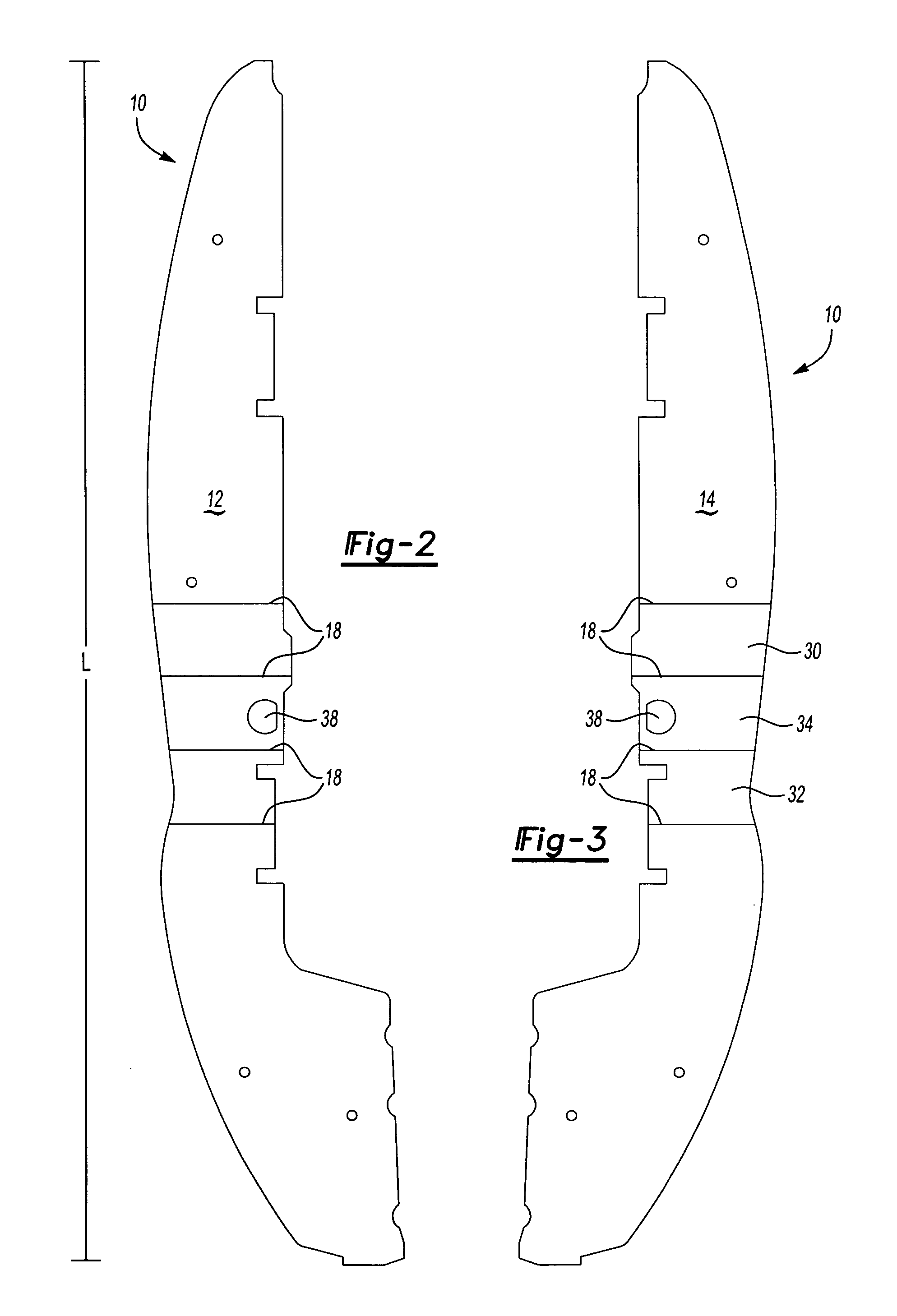
[0017] Referring to FIGS. 1-5, there is illustrated an exemplary baffle 10 formed in accordance with the present invention. The baffle 10 includes a first carrier layer 12, a second carrier layer 14 and a layer 16 of expandable material. The first carrier layer 12 opposes the second carrier layer 14 and is substantially coextensive therewith.
[0018] Each of the carrier layers 12, 14 include a plurality of bend locations 18. As used herein, unless otherwise stated, bend locations include actual bends of the carrier layer or deformations (e.g., scores, grooves, indents, markings, combination the...
PUM
| Property | Measurement | Unit |
|---|---|---|
| Temperature | aaaaa | aaaaa |
| Length | aaaaa | aaaaa |
| Interference | aaaaa | aaaaa |
Abstract
Description
Claims
Application Information