Electronic demarcating system

a technology of demarcation system and electronic demarcation device, which is applied in the direction of vehicle position/course/altitude control, process and machine control, instruments, etc., can solve the problems of not reaching the consumer until the tool is developed, the idea of developing working tools that can work automatically is old, and the robot lawnmower does not work in the wall area

a technology of demarcation system and electronic demarcation device, which is applied in the direction of vehicle position/course/altitude control, process and machine control, instruments, etc., can solve the problems of not reaching the consumer until the tool is developed, the idea of developing working tools that can work automatically is old, and the robot lawnmower does not work in the wall area

US20050230166A1Active Publication Date: 2005-10-20HUSQVARNA AB

Image

  • Electronic demarcating system
  • Electronic demarcating system
  • Electronic demarcating system

Examples


Embodiment Construction

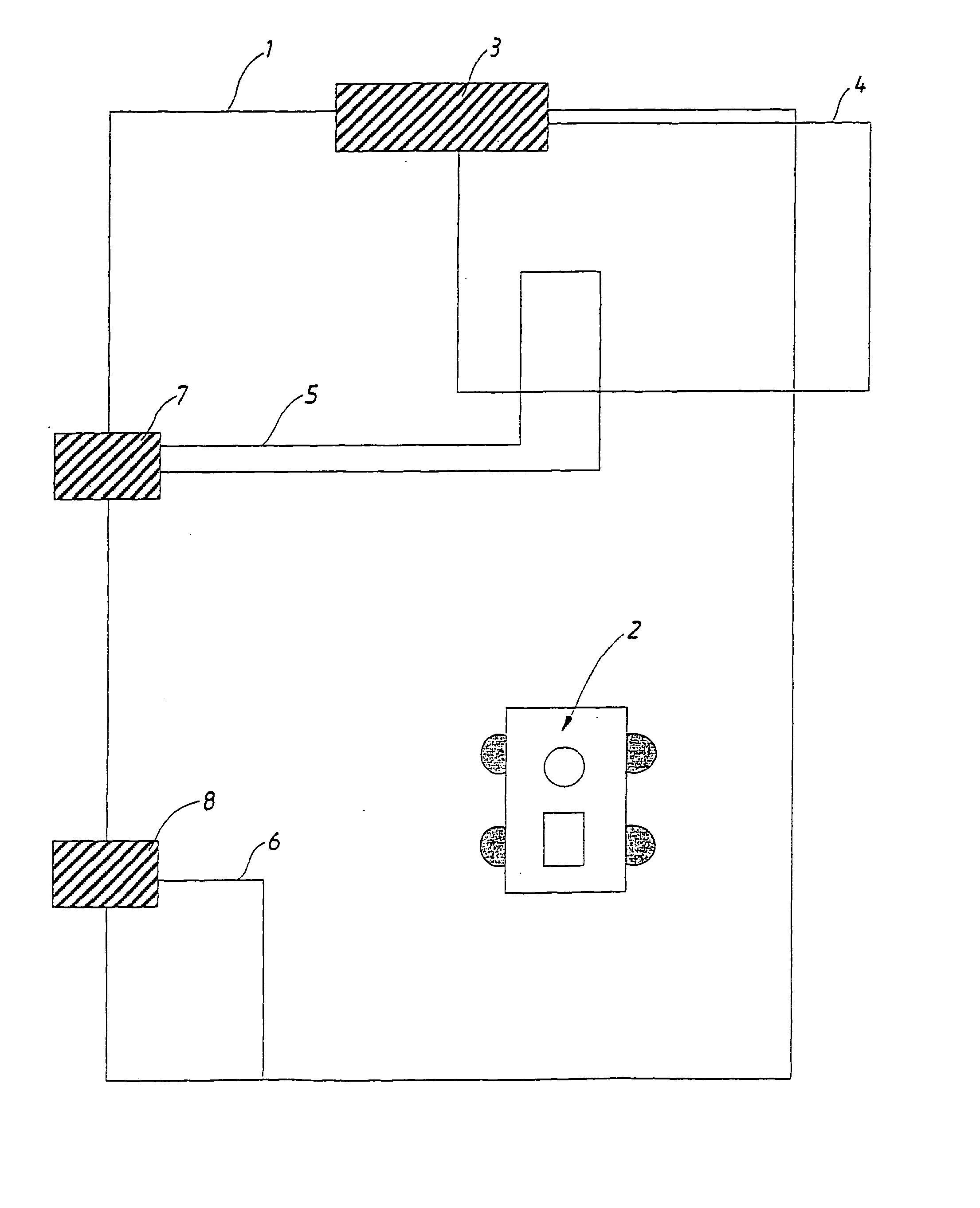
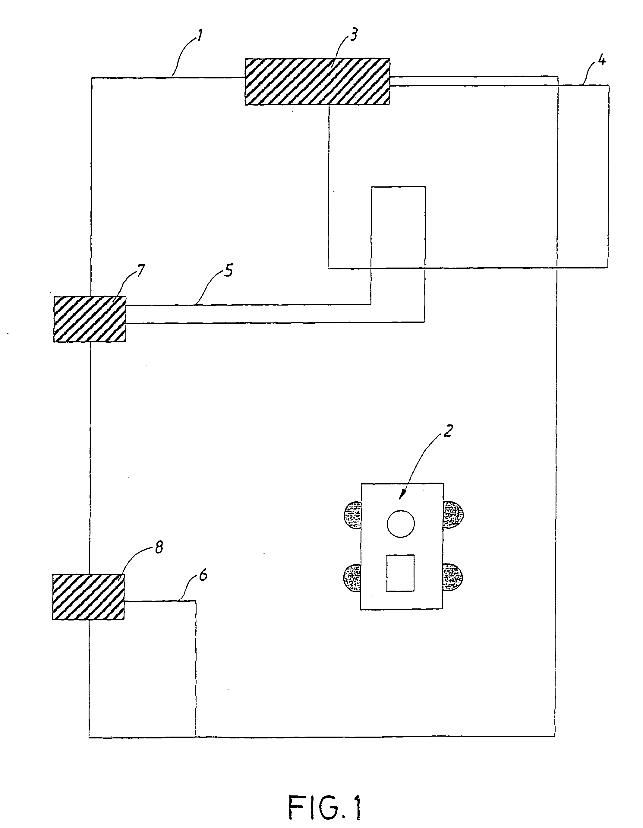
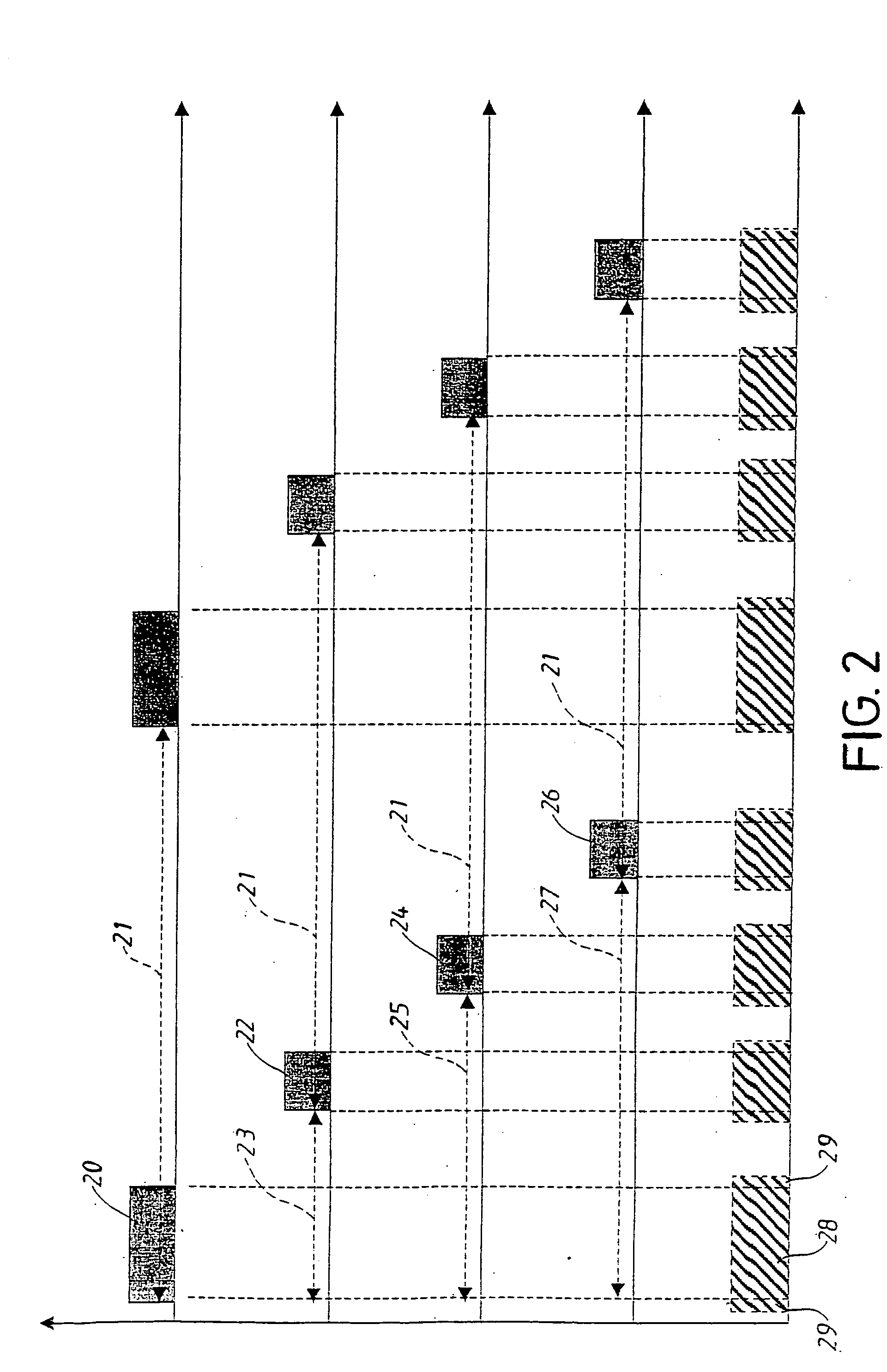
[0019] The figures show an illustrative embodiment of a search system according to the present invention. The illustrative embodiment should not be read as a restriction of the scope of the invention, since its purpose only is do illustrate one embodiment within the kind of search systems the present invention relates to. The purpose of the embodiment is to illustrate the scope of the invention.

[0020] In FIG. 1 a search system is shown. The system consists in an outer search cable 1 intended to enclose the area within which the robot 2 should move and operate. The outer cable comprises an electrical cable and a signal generator 3. The generator generates signals in the form of an electric current which is transmitted through said cable. The system of the illustrative embodiment moreover comprises three other search cables 4-6, which also consist in electrical cables. One of these 4 uses the same signal generator 3 but the others 5-6 each has one slave signal generator 7-8 each whic...


PUM


Abstract

The present invention relates to a method and an electronic search system for operating an automatic device, preferably an automatic lawnmower. The system comprises at least one first electrical cable (1, 4, 5, 6) connected to at least one first signal generator (3, 7, 8) and at least one sensing system arranged on said device. Said sensing system detects at least one magnetic field being transmitted via said cable (1, 4, 5, 6) and propagating through the air, the sensing system transmitting a processed signal to at least one driving means which contributes to the movements of said device in relation to a surface. Said search system comprises means by which the first signal generator (3, 7, 8) of the present invention transmits a current through said first cable (3, 7, 8), said current during a part of time being is in a state of rest where it is substantially constant, said state periodically being interrupted by at least one first characteristic current pulse.

Description

TECHNICAL FIELD [0001] The present invention relates to a method and an electronic search system for operating an automatic device, preferably an automatic lawnmower. The system comprises at least one first electrical cable connected to at least one first signal generator and at least one sensing system arranged on said device. Said sensing system detects at least one magnetic field being transmitted via said cable and propagating through the air, the sensing system transmitting a processed signal to at least one driving means which contributes to the movements of said device in relation to a surface. BACKGROUND [0002] The idea of developing working tools that can work automatically is old. Such tools are for instance robots for vacuum cleaning or to cut grass. Despite the fact that this is an old idea, such tools have not reached the consumer until recently. One example is the robotic vacuum cleaner Trilobiteâ„¢ and the automatic lawnmower Automowerâ„¢. Both of these treat (cut or clea...

Claims


Application Information

Patent Timeline
20 Oct 2005
Publication
US20050230166A1
IPC
A01D34/00; G05D1/02
CPC
A01D34/008; A01D2101/00; G05D2201/0208; G05D1/0265; G05D1/0225
Inventors
PETERSSON, ULF; BERGVALL, BENGT-ALLAN