
Electronic demarcating system

a technology of electronic demarcation system and electronic demarcation device, which is applied in the direction of automatic call-answering/message-recording/conversation-recording, navigation instruments, program control, etc., can solve the problems of not reaching the consumer until the tool is developed, the idea of developing working tools that can work automatically is old, and the robot lawnmower does not work in the area defined by walls

Active Publication Date: 2009-11-03
HUSQVARNA AB
View PDF15 Cites 63 Cited by
  • Summary
  • Abstract
  • Description
  • Claims
  • Application Information

AI Technical Summary

Problems solved by technology

The idea of developing working tools that can work automatically is old.
Despite the fact that this is an old idea, such tools have not reached the consumer until recently.
Robotic lawnmowers on the other hand do not work in areas defined by walls.
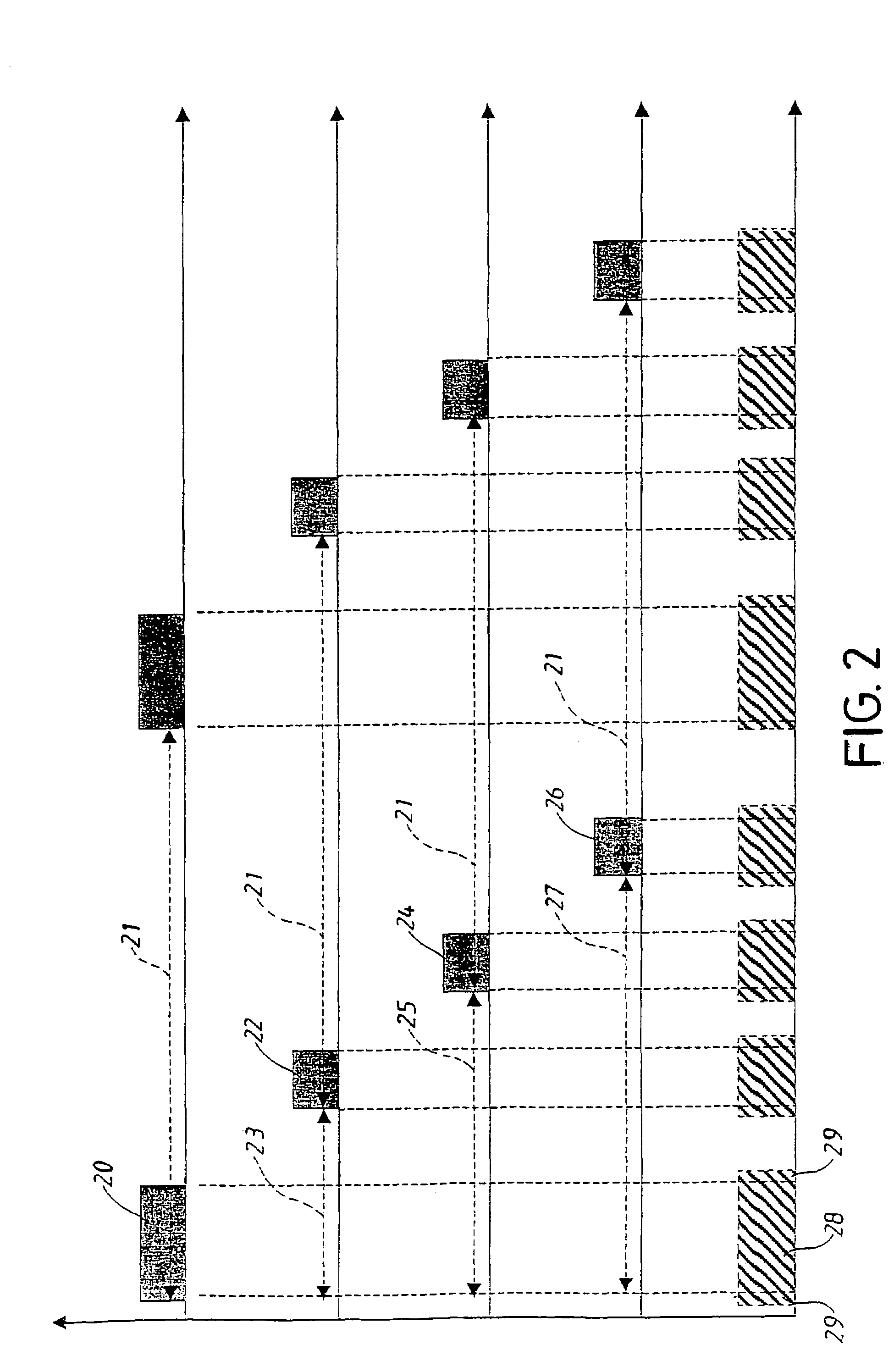
A scarcity with present search systems for automatic robots is that they use an uninterrupted current (such as one or several sinus waves) in order to generate the magnetic signals.
Such disturbing field can confuse the sensing system and thereby cause operating problems for the robot.
Especially signals from other similar search systems, such as the next-door neighbours' system, could cause such operating problems since both systems may operate within the same frequency band.
The search systems will interfere with each other since the fields are added.
Another problem with present search systems is that the costs for sinus wave systems has increased since these often requires trimming of the frequency defining components.

Method used


Image

  • Electronic demarcating system
  • Electronic demarcating system
  • Electronic demarcating system

Examples


Embodiment Construction

[0020]The figures show an illustrative embodiment of a search system according to the present invention. The illustrative embodiment should not be read as a restriction of the scope of the invention, since its purpose only is do illustrate one embodiment within the kind of search systems the present invention relates to. The purpose of the embodiment is to illustrate the scope of the invention.

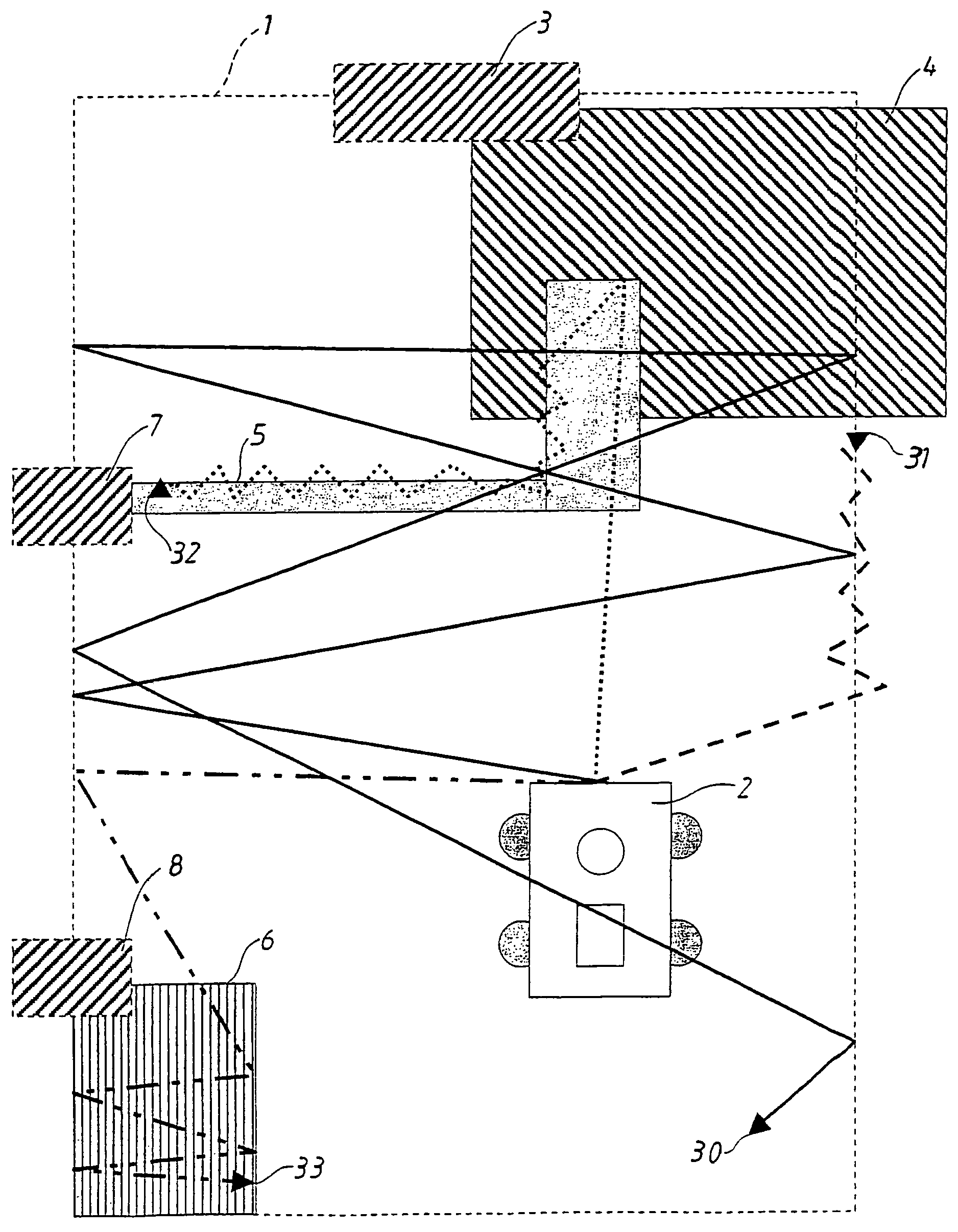
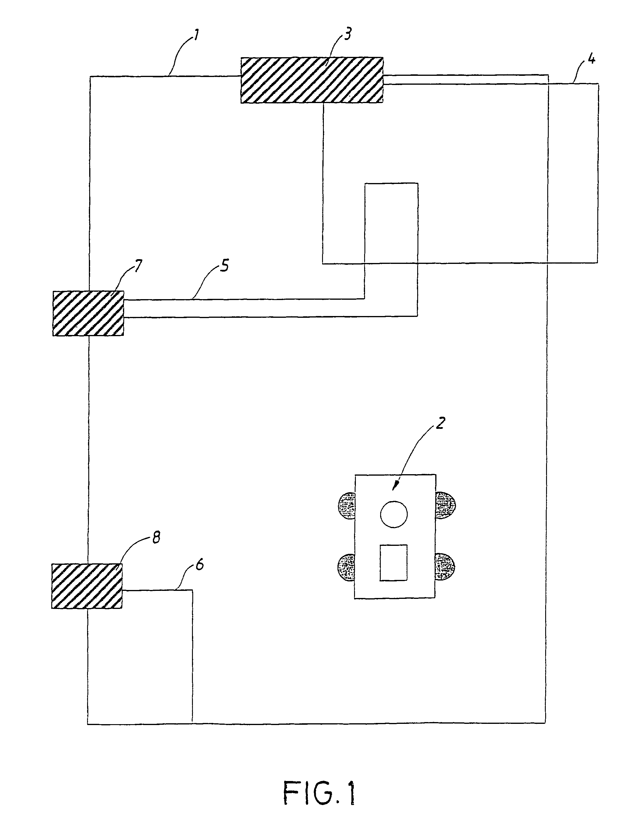
[0021]In FIG. 1 a search system is shown. The system consists in an outer search cable 1 intended to enclose the area within which the robot 2 should move and operate. The outer cable comprises an electrical cable and a signal generator 3. The generator generates signals in the form of an electric current which is transmitted through said cable. The system of the illustrative embodiment moreover comprises three other search cables 4-6, which also consist in electrical cables. One of these 4 uses the same signal generator 3 but the others 5-6 each has one slave signal generator 7-8 each which g...


PUM


Abstract

A method and an electronic search system for operating an automatic device, preferably an automatic lawnmower. The system comprises at least one first electrical cable (1,4,5,6) connected to at least one first signal generator (3,7,8) and at least one sensing system arranged on said device. Said sensing system detects at least one magnetic field being transmitted via said cable (1,4,5,6) and propagating through the air, the sensing system transmitting a processed signal to at least one driving element which contributes to the movements of said device in relation to a surface.

Description

[0001]This application claims the benefit of International Application Number PCT / SE03 / 00916, which was published in English on Dec. 18, 2003.TECHNICAL FIELD[0002]The present invention relates to a method and an electronic search system for operating an automatic device, preferably an automatic lawnmower. The system comprises at least one first electrical cable connected to at least one first signal generator and at least one sensing system arranged on said device. Said sensing system detects at least one magnetic field being transmitted via said cable and propagating through the air, the sensing system transmitting a processed signal to at least one driving means which contributes to the movements of said device in relation to a surface.BACKGROUND[0003]The idea of developing working tools that can work automatically is old. Such tools are for instance robots for vacuum cleaning or to cut grass. Despite the fact that this is an old idea, such tools have not reached the consumer unti...

Claims


Application Information

Patent Timeline
Patent Type & Authority Patents(United States)
IPC IPC(8): G06F19/00A01D34/00G05D1/02
CPCA01D34/008G05D1/0265A01D2101/00G05D2201/0208G05D1/0225
Inventor PETERSSON, ULFBERGVALL, BENGT-ALLAN
Owner HUSQVARNA AB
Learn More