System and method for position determination of objects

a position determination and object technology, applied in the field of methods and systems for position determination, can solve problems such as difficult detection or serious degree of uncertainty in measurement, inability to determine the position of chips in different parts of the room, and complicated signal processing, so as to improve the measurement of position

Active Publication Date: 2005-06-30
SONITOR TECH
View PDF8 Cites 62 Cited by
  • Summary
  • Abstract
  • Description
  • Claims
  • Application Information

AI Technical Summary

Benefits of technology

[0015] The present invention relates to a method and a system for surveillance and position determination of objects in rooms. The object of the invention is to improve the measurem...

Problems solved by technology

A weakness of the system is that it cannot determine the position of chips in different parts of a room.
The drawback of these systems is that they require precise localisation of all the receivers in advance, complicated signal processing and they only work when there is an unobstructed view between transmitter and receivers.
These may transmit a constant tone between 20 and 50 kHz, and if the...

Method used


Image

  • System and method for position determination of objects
  • System and method for position determination of objects
  • System and method for position determination of objects

Examples


Embodiment Construction

[0025] The system according to the invention is constructed in such a manner that it should be influenced as little as possible by noise sources and should correct for Doppler effect due to movement of the transmitter units. There are several technical features of transmitter, receiver and central unit that contribute to this. In its entirety it represents a system, which is well suited to environments with various noise sources, and which can be used even though the chips transmitting signals are in motion.

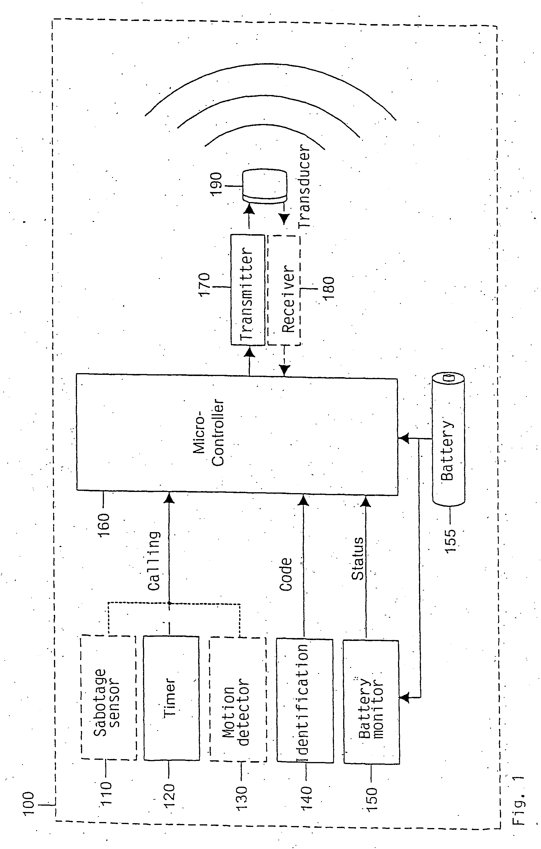
[0026]FIG. 1 illustrates which units may normally be incorporated in each transmitter unit 100, also called a chip. Each chip 100 is a unit, which may contain a sabotage sensor 110, a timer 120, a motion detector 130, an identification chip 140, a battery monitor 150, a microcontroller 160, a transmitter 170 and a receiver 180, and which transmits ultrasound waves by means of a transducer 190. The whole unit is supplied with power from a battery 155. The units are incorporated i...


PUM


Abstract

A method and a system (400) for detection and position determination of chips (100), which transmit ultrasound signals in a room. The system (400) comprises electronic identification chips (100), which are attached to objects that have to be monitored. Each chip (100) is equipped with a transmitter (179) and a receiver (180). The signals are received by a plurality of detector units (290), which are connected to a detector base unit (200) that registers and interprets the signals transmitted form the identification chips (100). Detector base units (200) located in different rooms are interconnected in a network (215) and transmit processed information to one or more central units (410) for further interpretation and sorting. The special feature of the invention is that line interference is substantially removed, and it is possible to determine position even though the identification chips (100) are in motion.

Description

INTRODUCTION / TECHNICAL FIELD [0001] The invention relates to a method and a system for surveillance and position determination of objects and / or living beings within a restricted area, such as, e.g., a room in a building. The system comprises a plurality of electronic identification chips that are attached to the objects which have to be monitored. Each chip has its own identification code (ID code) and is equipped with its own ultrasound transmitter and receiver. The system further comprises a plurality of detectors in each room for registering and interpreting the signals transmitted from the chips. The detectors are interconnected in a network and transmit the information received to one or more central units also included in the system for further processing and sorting. By means of the invention line interference from electrical equipment, which may arise when the signals are transmitted from transmitter units to detectors, will be substantially removed, in addition to which it...

Claims


Application Information

Patent Timeline
IPC IPC(8): G01S7/00G01S15/10G01S15/74
CPCG01S7/003G01S15/74G01S15/102
Inventor HOLM, SVERRAHOLM, RUNE
Owner SONITOR TECH
Why Eureka
Try Eureka