Radiation monitoring system

a radiation monitoring and monitoring system technology, applied in the field of radiation monitoring systems, can solve the problems of corneal dystrophies, instruments are disadvantageous, and excessive radiation exposure can be hazardous to one's health

Inactive Publication Date: 2005-10-20
HOWELL THOMAS A +3
View PDF99 Cites 135 Cited by
  • Summary
  • Abstract
  • Description
  • Claims
  • Application Information

AI Technical Summary

Benefits of technology

[0008] In one embodiment, the eyewear includes a detector, electrical circuitry and an output device. The eyewear can also include one or both of a battery and a solar cell to provide power to the electrical circuitry and possibly other components. Further, the eyewear can also include one or more additional sensors. Still further, the eyewear can also include communication capabilities.

Problems solved by technology

Often excessive exposure to radiation can be hazardous to one's health.
However, UV-A has also been found to play some role in skin cancer and is the cause of eye cataracts, solar retinitis, and corneal dystrophies.
Although several UV radiation measuring and warning instruments have been developed and made commercially available, these instruments are disadvantageous for various reasons.
One disadvantage is that the instruments are often a stand alone, special purpose device.
As a result, a user must separately wear the special purpose device, which can be intrusive and often inconvenient.
Another disadvantage is that those instruments, even if separate but attachable to other devices, hinder or impede the design for the devices.

Method used


Image

  • Radiation monitoring system
  • Radiation monitoring system
  • Radiation monitoring system

Examples


Embodiment Construction

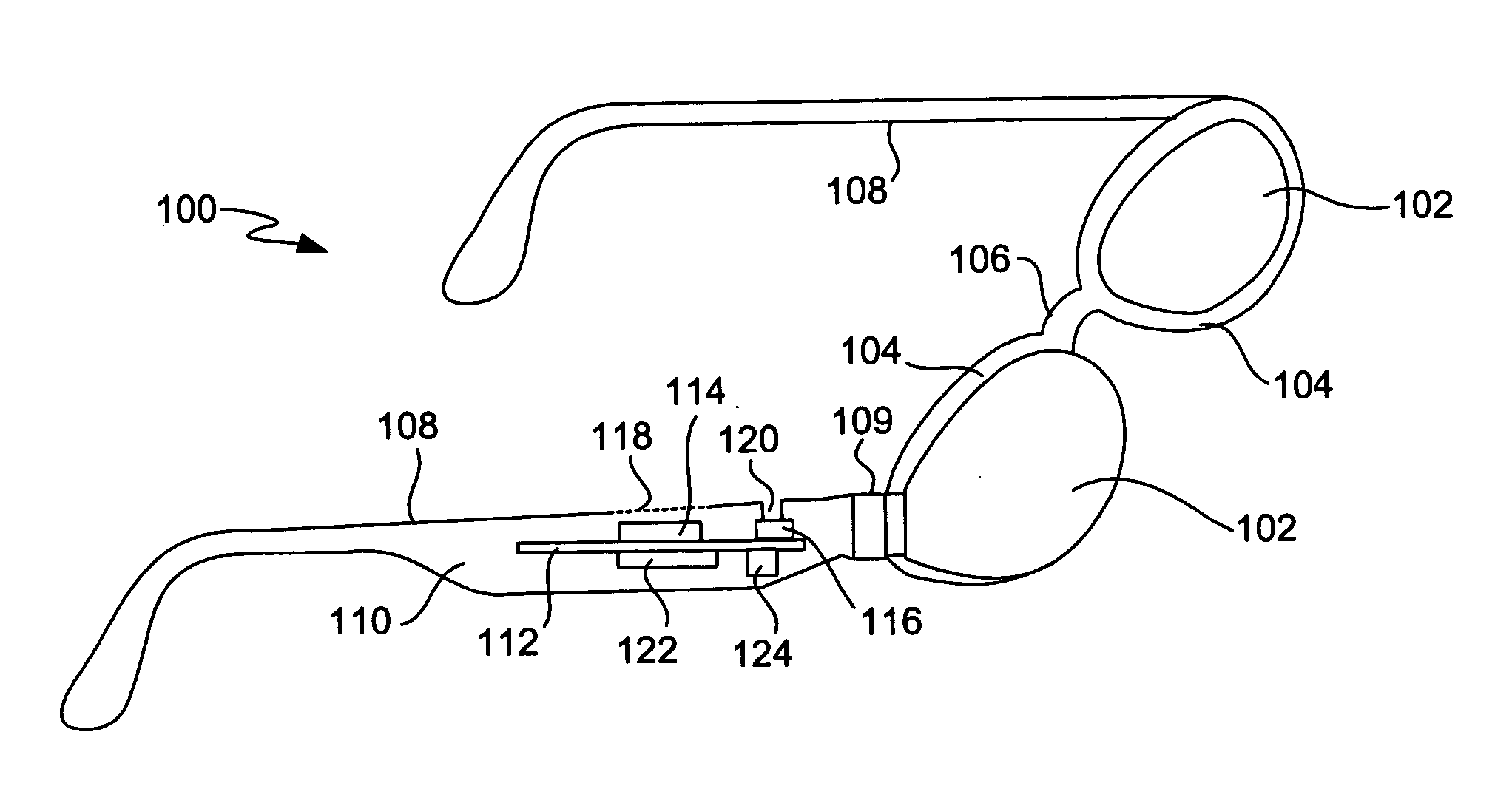
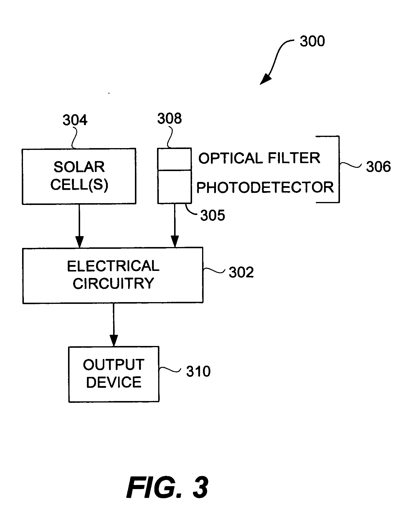
[0067] In one embodiment, an electronic circuit having radiation monitoring capability. Radiation, such as ultraviolet (UV) radiation, infrared (IR) radiation or light, can be measured by the electronic circuit. The measured radiation can then be used in providing radiation-related information to a user of the electronic circuit.

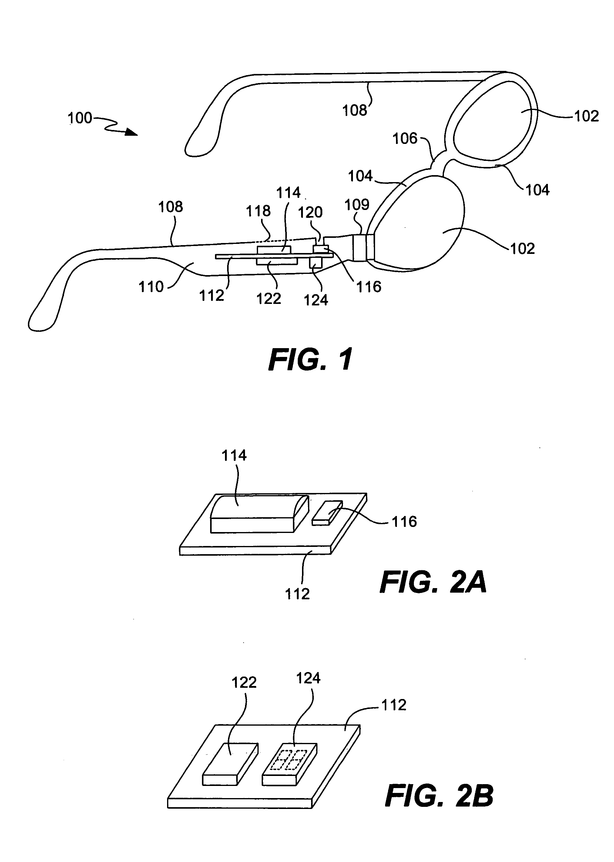
[0068] In one embodiment, all components for monitoring radiation can be integrated with eyewear, such as a frame (e.g., a temple of the frame) of the eyewear. Since any of the components provided can be integrated with the eyewear, the disturbance to design features of the eyewear can be reduced. As an example, the eyewear normally includes a pair of temples, and the components for monitoring radiation can be embedded within one or both of the temples. In one implementation, all components for monitoring radiation are integrated into a temple of the frame of the eyewear. As an example, these components can be formed together on a substrate as a module.

[00...


PUM

PropertyMeasurementUnit
wavelengthsaaaaaaaaaa
timeaaaaaaaaaa
timeaaaaaaaaaa

Abstract

An electronic circuit having radiation monitoring capability is disclosed. Radiation, such as ultraviolet (UV) radiation, infrared (IR) radiation or light, can be measured by the electronic circuit. The measured radiation can then be used in providing radiation-related information to a user of the electronic circuit. In one implementation, the electronic circuit is provided within eyewear so that the user of the eyewear is able to easily monitor their exposure to radiation.

Description

CROSS-REFERENCE TO RELATED APPLICATIONS [0001] The application claims priority to: (i) U.S. Provisional Patent Application No. 60 / 562,798, filed Apr. 15, 2004, entitled “EYEWEAR WITH ULTRAVIOLET DETECTION SYSTEM,” and which is hereby incorporated herein by reference; (ii) U.S. Provisional Patent Application No. 60 / 583,169, filed Jun. 26, 2004, entitled “ELECTRICAL COMPONENTS FOR USE WITH EYEWEAR, AND METHODS THEREFOR,” and which is hereby incorporated herein by reference; (iii) U.S. Provisional Patent Application No. 60 / 592,045, filed Jul. 28, 2004, entitled “EYEGLASSES WITH A CLOCK OR OTHER ELECTRICAL COMPONENT,” and which is hereby incorporated herein by reference; (iv) U.S. Provisional Patent Application No. 60 / 605,191, filed Aug. 28, 2004, entitled “ELECTRICAL COMPONENTS FOR USE WITH EYEWEAR, AND METHODS THEREFOR,” and which is hereby incorporated herein by reference; (v) U.S. Provisional Patent Application No. 60 / 618,107, filed Oct. 12, 2004, and entitled “TETHERED ELECTRICAL C...

Claims


Application Information

Patent Timeline
Patent Type & Authority Applications(United States)
IPC IPC(8): G02C5/00G02C11/00G03C1/00
CPCG02C11/00G02C5/001
Inventor HOWELL, THOMAS A.CHAO, DAVIDTHOMAS, C. DOUGLASSTONG, PETER P.
Owner HOWELL THOMAS A
Why Eureka
Try Eureka