
Magnetic tunnel junction structures having bended tips at both ends thereof, magnetic random access memory cells employing the same and photomasks used in formation thereof

a tunnel junction and magnetic technology, applied in the direction of heat-activated film/foil adhesives, instruments, film/foil adhesives, etc., can solve the problems of non-uniform switching characteristics of mtj structures, limited improvement of writing margins, and complex manufacturing processes of mtj structures by higo

Inactive Publication Date: 2005-10-20
SAMSUNG ELECTRONICS CO LTD
View PDF10 Cites 12 Cited by
  • Summary
  • Abstract
  • Description
  • Claims
  • Application Information

AI Technical Summary

Benefits of technology

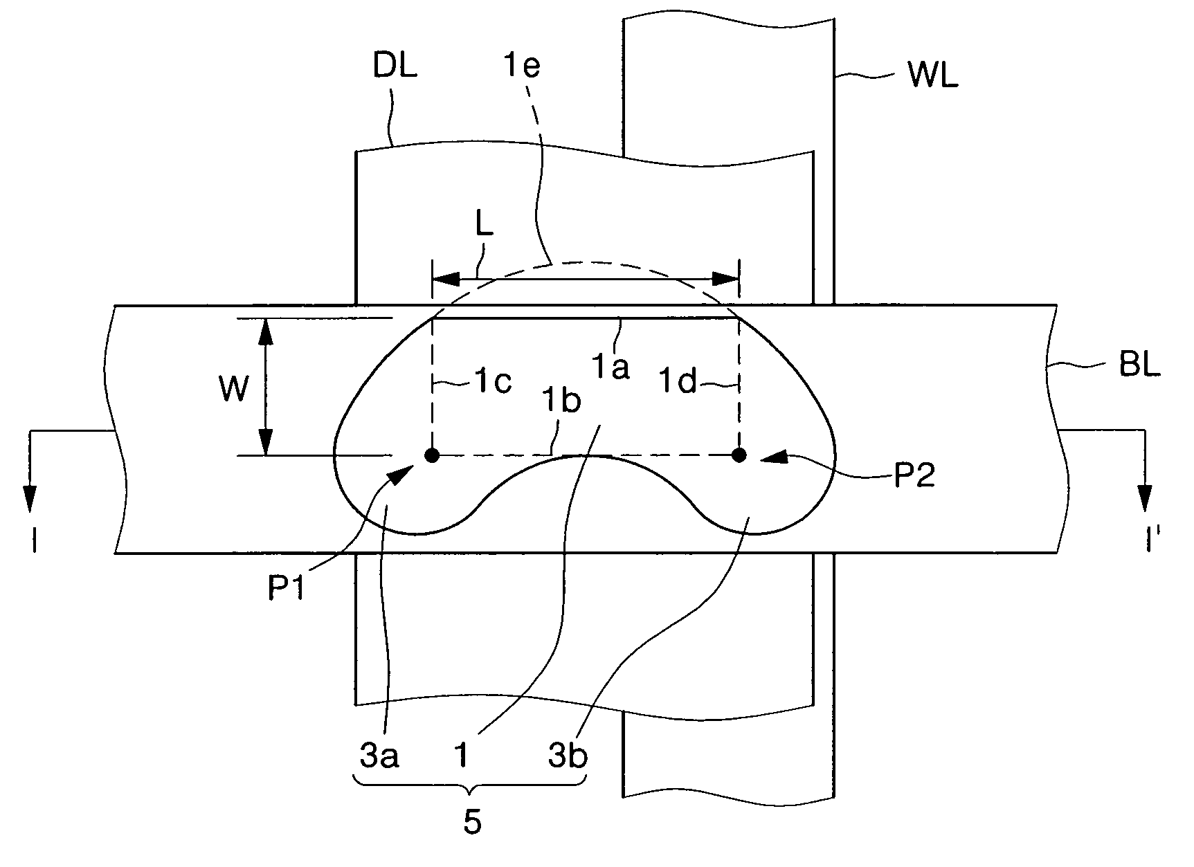
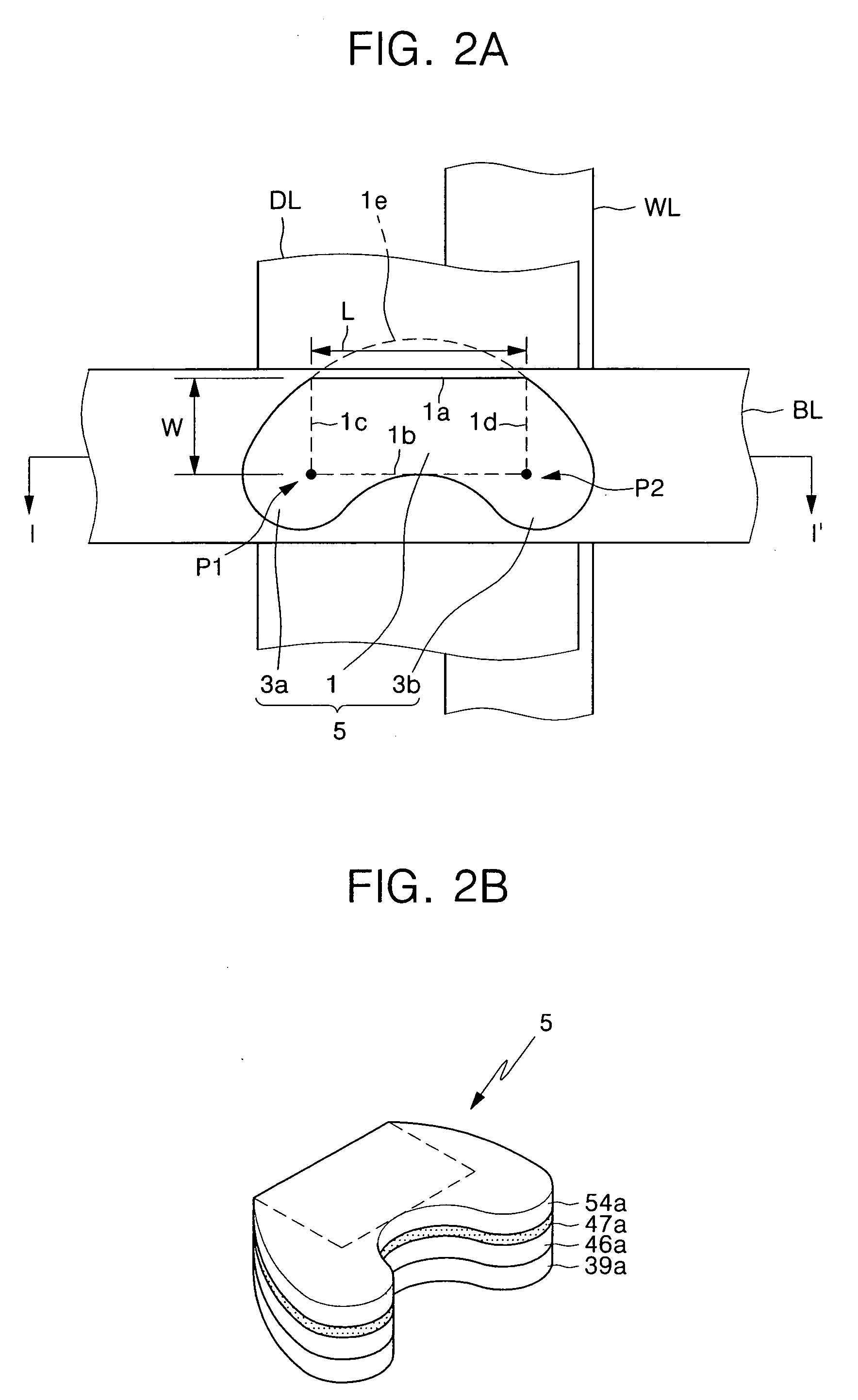
The invention is about magnetic tunnel junction structures with bended tips at both ends. These structures include a pinned layer pattern, a tunneling insulation layer pattern, and a free layer pattern. The free layer pattern has first and second tips protruding from both ends of a main body. The main body has first and second sides facing each other, and third and fourth sides facing each other. The first tip is in contact with the second and third sides, and the second tip is in contact with the second and fourth sides. The magnetic tunnel junction structures can be used in MRAM cells and can be formed using photo masks. The technical effects of the invention include improved performance and reliability of magnetic tunnel junction structures and simplified manufacturing process.

Problems solved by technology

The plurality of MTJ structures may exhibit non-uniform switching characteristics according to a fabrication process thereof.
Nevertheless, in the event that the MTJ structure according to Engel et al. has a rectangular or ellipse shape when viewed from a plan view, there may be some limitations in improving the writing margin.
Accordingly, the MTJ structure by Higo may require a complex manufacturing process.
This may lead to an increase of power consumption during a writing operation.

Method used


Image

  • Magnetic tunnel junction structures having bended tips at both ends thereof, magnetic random access memory cells employing the same and photomasks used in formation thereof
  • Magnetic tunnel junction structures having bended tips at both ends thereof, magnetic random access memory cells employing the same and photomasks used in formation thereof
  • Magnetic tunnel junction structures having bended tips at both ends thereof, magnetic random access memory cells employing the same and photomasks used in formation thereof

Examples


examples

[0084] Hereinafter, switching characteristics of magnetic tunnel junction structures fabricated according to the above-described embodiments and the conventional art will be described.

[0085]FIG. 12 is a graph illustrating measurement results of asteroid curves that exhibit switching characteristics of magnetic tunnel junction structures fabricated according to a conventional art. In FIG. 12, the abscissa denotes a normalized hard magnetic field Hh / Hc with respect to a coercive magnetic field Hc, and the ordinate denotes a normalized easy magnetic field He / Hc with respect to the coercive magnetic field Hc. Here, the coercive magnetic field Hc means a minimum easy magnetic field required to switch the conventional magnetic tunnel junction structure without any application of the hard magnetic field.

[0086] Conventional magnetic tunnel junction structures exhibiting the measurement results of FIG. 12 were fabricated to have a rectangular shape when viewed from a plan view. In detail, ...


PUM


Abstract

Provided are magnetic tunnel junction structures having bended tips at both ends thereof, magnetic RAM cells employing the same and photo masks used in formation thereof. The magnetic tunnel junction structures have a pinned layer pattern, a tunneling insulation layer pattern and a free layer pattern, which are stacked on an integrated circuit substrate. At least the free layer pattern has a main body as well as first and second bended tips each protruded from both ends of the main body when viewed from a plan view.

Description

CROSS-REFERENCE TO RELATED APPLICATION [0001] This application claims the benefit of Korean Patent Application No. 2004-26689, filed Apr. 19, 2004, the contents of which are hereby incorporated herein by reference in their entirety. BACKGROUND OF THE INVENTION [0002] 1. Field of the Invention [0003] The present invention relates to magnetic random access memory (MRAM) devices and, more particularly, to magnetic tunnel junction structures having bended tips at both ends thereof, MRAM cells employing the same, and photo masks used in formation thereof. [0004] 2. Description of the Related Art [0005] MRAM devices have been widely used as nonvolatile memory devices, which can be operated at a low voltage and at a high speed. In a unit cell of the MRAM devices, data is stored in a magnetic tunnel junction (MTJ) structure of a magnetic resistor. The MTJ structure includes first and second ferromagnetic layers and a tunneling insulation layer interposed therebetween. Magnetic polarization ...

Claims


Application Information

Patent Timeline
Patent Type & Authority Applications(United States)
IPC IPC(8): G11C11/16G11C11/15H01L21/8246H10N39/00H01L27/22H01L29/82H10N50/10
CPCB82Y10/00H01L43/08H01L27/228G11C11/16H10B61/22H10N50/10G11C11/161G11C11/15H10N50/85H10N50/01H10B61/00
Inventor HA, YOUNG-KILEE, JANG-EUNOH, SE-CHUNGBAE, JUN-SOOKIM, HYUN-JONAM, KYUNG-TAE
Owner SAMSUNG ELECTRONICS CO LTD
Learn More