Direct Drive Wind Turbine

a direct drive, wind turbine technology, applied in the direction of electric generator control, machines/engines, mechanical equipment, etc., can solve the problems of difficulty in both manufacturing and maintaining the wind turbin

Active Publication Date: 2005-10-20
NORTHERN POWER SYSTEMS INC
View PDF13 Cites 107 Cited by
  • Summary
  • Abstract
  • Description
  • Claims
  • Application Information

AI Technical Summary

Problems solved by technology

This often results in difficulties in both manufacturing the wind turbine and in conducting maintenance operations in the nacelle once the wind turbine is installed.

Method used


Image

  • Direct Drive Wind Turbine
  • Direct Drive Wind Turbine
  • Direct Drive Wind Turbine

Examples


Embodiment Construction

[0016] Electrical power may be generated by many different methods. The most common methods involve the boiling of water using fossil or nuclear based fuels. The steam produced by the boiling is used to rotate a turbine that drives an electrical generator to create the electrical power. While these common methods are very efficient, they also have undesirable side effects, such as the production of toxic pollutants, or the rely on a dwindling natural resource. One alternate method of creating electrical power is to harness a renewable natural resource such as the wind to be a driving force to rotate the electrical generator to produce the electricity.

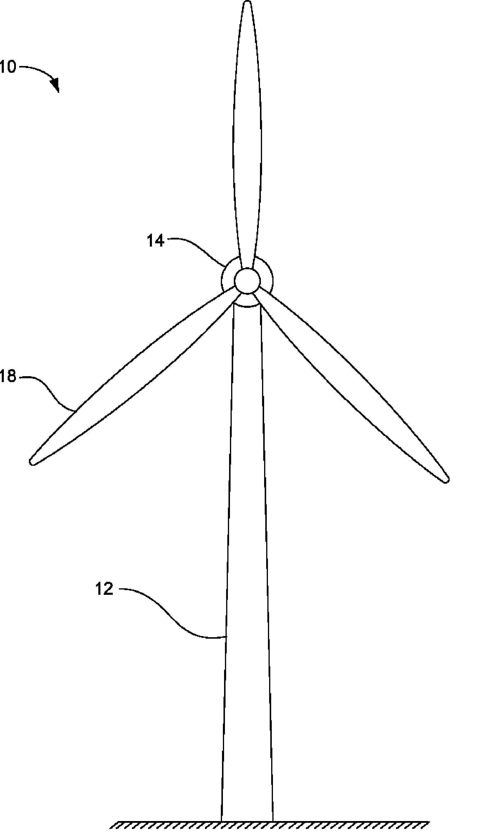
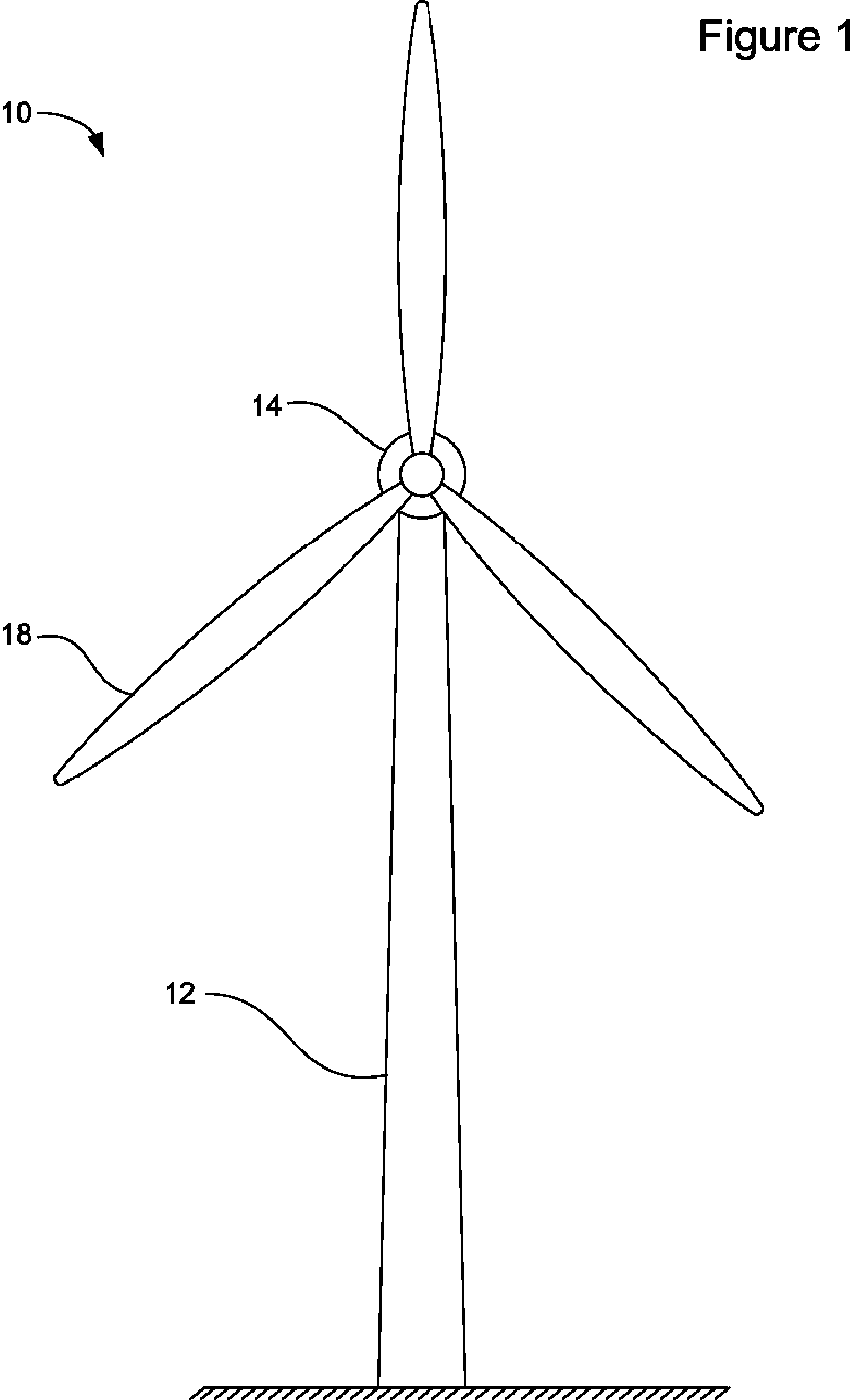
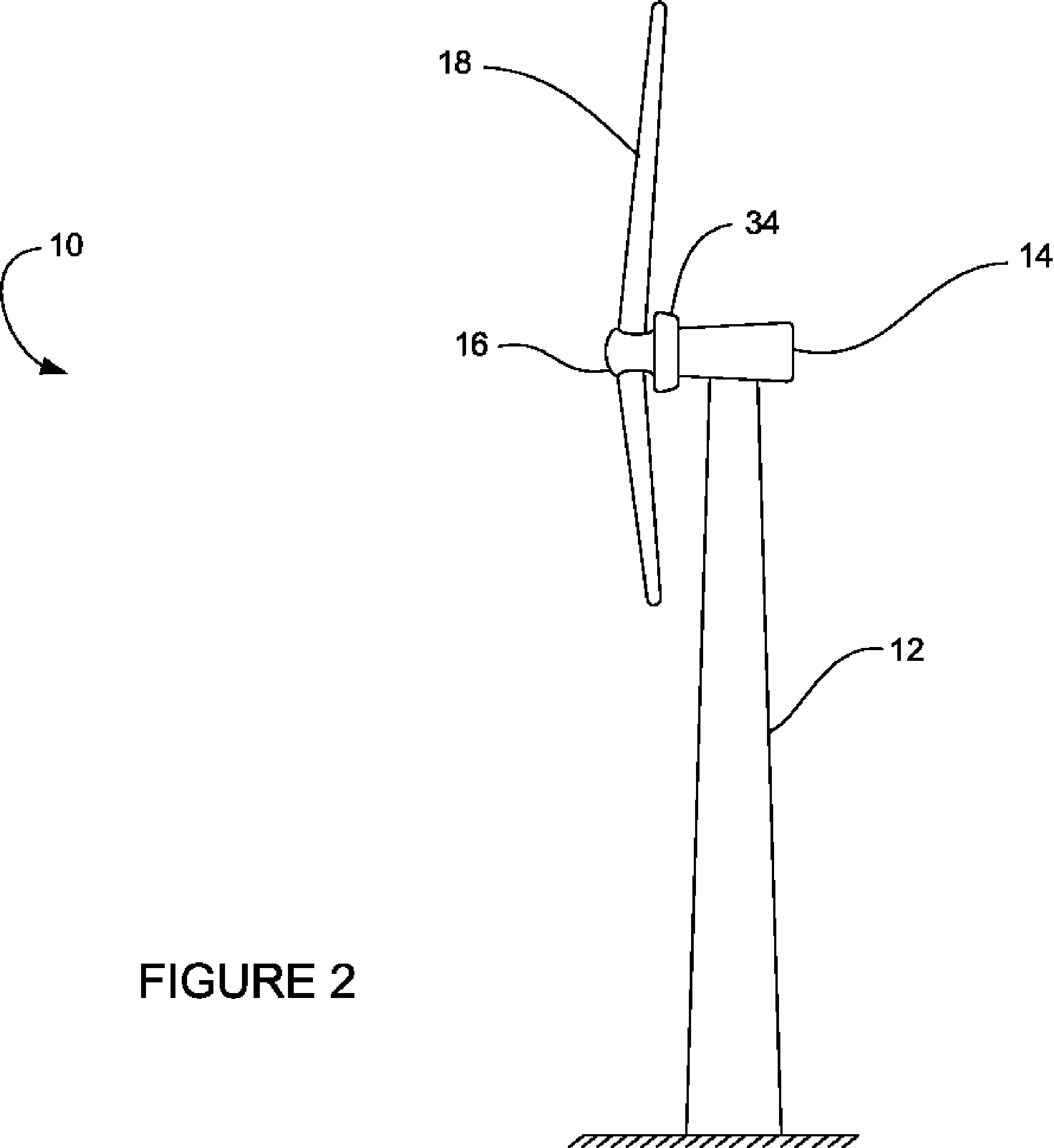
[0017] Referring to FIG. 1 and FIG. 2, a wind turbine 10 capable of generating electrical power in the 100 kW to 2000 kW range is shown. The wind turbine 10 is includes a tower 12 which is anchored to the ground by means of a bolted connection to a steel and concrete foundation. On the opposing end of the tower 12, the nacelle 14 is mo...


PUM


Abstract

A wind turbine is provided that minimizes the size of the drive train and nacelle while maintaining the power electronics and transformer at the top of the tower. The turbine includes a direct drive generator having an integrated disk brake positioned radially inside the stator while minimizing the potential for contamination. The turbine further includes a means for mounting a transformer below the nacelle within the tower.

Description

FEDERAL RESEARCH STATEMENT [0001] This invention was made with Government support under contract DE-FC36-03GO13131 awarded by the Department of Energy. The Government has certain rights in this invention.FIELD OF INVENTION [0002] This disclosure relates generally to wind turbine and especially to wind turbines with a direct connection between the turbine and the electrical generator. BACKGROUND OF INVENTION [0003] The wind has historically been one of the most widely used natural resources to provide the energy necessary to power our needs. As the demand for energy has increased and the supplies of fossil dwindled, the result has been a renewed look by electrical utility companies at alternative methods for producing electrical power. One method of electrical production involves the harnessing of wind by a turbine to drive an electrical generator. [0004] Wind turbines typically involve using a series of blades fixed to the top of a tower to rotate about a horizontal axis. The blades...

Claims


Application Information

Patent Timeline
Patent Type & Authority Applications(United States)
IPC IPC(8): F03D7/02F03D9/00F03D11/00
CPCF03D7/0248F03D9/002F03D11/0008F05B2220/7066F05B2240/14H02K7/1838H02K13/003Y02E10/722Y02E10/723Y02E10/725H02K7/102F03D80/70F03D9/25Y02E10/72
Inventor BYWATERS, GARRETTDANFORTH, WILLIAMBEVINGTON, CHRISTOPHERSTOWELL, JESSECOSTIN, DANIEL
Owner NORTHERN POWER SYSTEMS INC
Why Eureka
Try Eureka