Modular regenerative braking

a regenerative braking and modular technology, applied in the field of regenerative assisted braking, can solve problems such as energy depletion, and achieve the effects of reducing the number of electrical devices used, reducing the cost and complexity of the modular braking unit, and reducing the number of electrical devices

Inactive Publication Date: 2005-10-20
KELSEY HAYES CO
View PDF11 Cites 26 Cited by
  • Summary
  • Abstract
  • Description
  • Claims
  • Application Information

AI Technical Summary

Benefits of technology

[0007] The present invention has the advantage of reducing the number of three-way proportional valves and pressure sensors required to sense pressure at each proportional valve which reduces the cost and complexity of the modular braking unit. Furthermore, because of the reduction of the number of electrical devices used in the modular braking unit, less energy will be required to maintain operation of the electrical devices which is productive when using regenerative braking. Moreover, the above modular braking unit is compatible with regenerative braking and low cost conventional modular slip control HCU's.
[0008] In one aspect of the invention, a brake module provides a first (pump) circuit of pressurized brake fluid and a second (brake) and a third (brake) circuit of pressurized brake fluid. A first set of brake actuators is operated by the application of pressurized brake fluid and a second set of brake actuators is operated by the application of pressurized brake fluid. A first fluid separator unit is coupled to the first circuit and the second circuit for substantially preventing the intermixing of pressurized brake fluid between the first circuit and the second circuit. The first fluid separator unit includes a moveable pressure boundary which enables, through movement thereof, the second circuit of pressurized brake fluid to selectively act upon the first set of brake actuators in response to the first circuit of pressurized brake fluid acting upon the first fluid separator unit. A second fluid separator unit is coupled to the first circuit and the third circuit for substantially preventing the intermixing of pressurized brake fluid of the first circuit and the third circuit. The second fluid separator unit includes a moveable pressure boundary which enables, through movement thereof, the third circuit of pressurized brake fluid to selectively act upon the second set of brake actuators in response to the first circuit of pressurized brake fluid acting upon the second fluid separator unit. At least one proportional valve selectively controls the pressurized brake fluid of the first circuit acting on the first and the second fluid separator units.

Problems solved by technology

The use of electrical energy for energizing each electrical component within the electric-hydraulic braking system results in energy depletion.
The more electrical devices within a system, the more the power consumption which is ultimately counter-productive to a system used in cooperation with regenerative braking being that the primary purpose of the regenerative braking is to recapture energy.

Method used


Image

  • Modular regenerative braking
  • Modular regenerative braking
  • Modular regenerative braking

Examples


Embodiment Construction

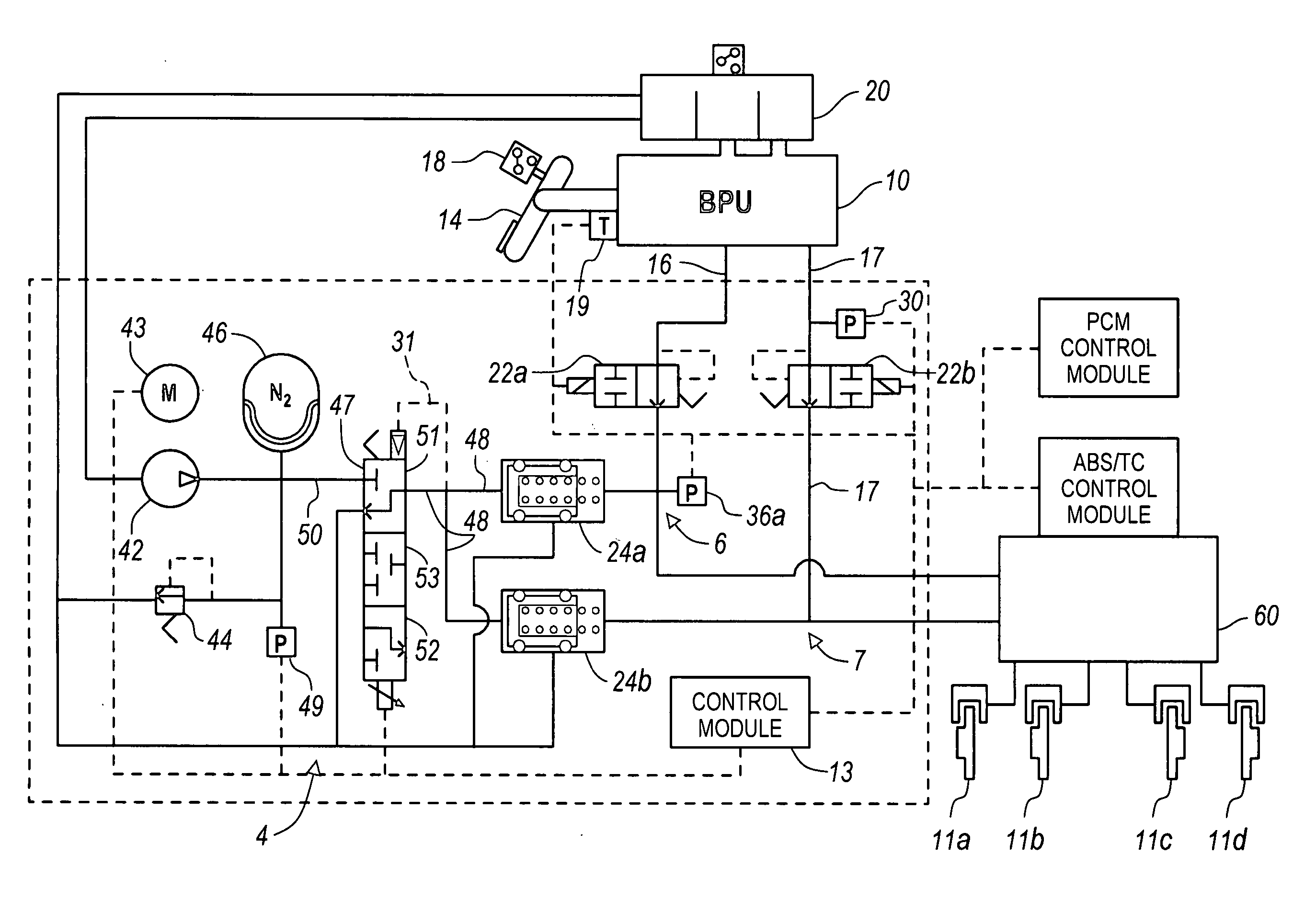
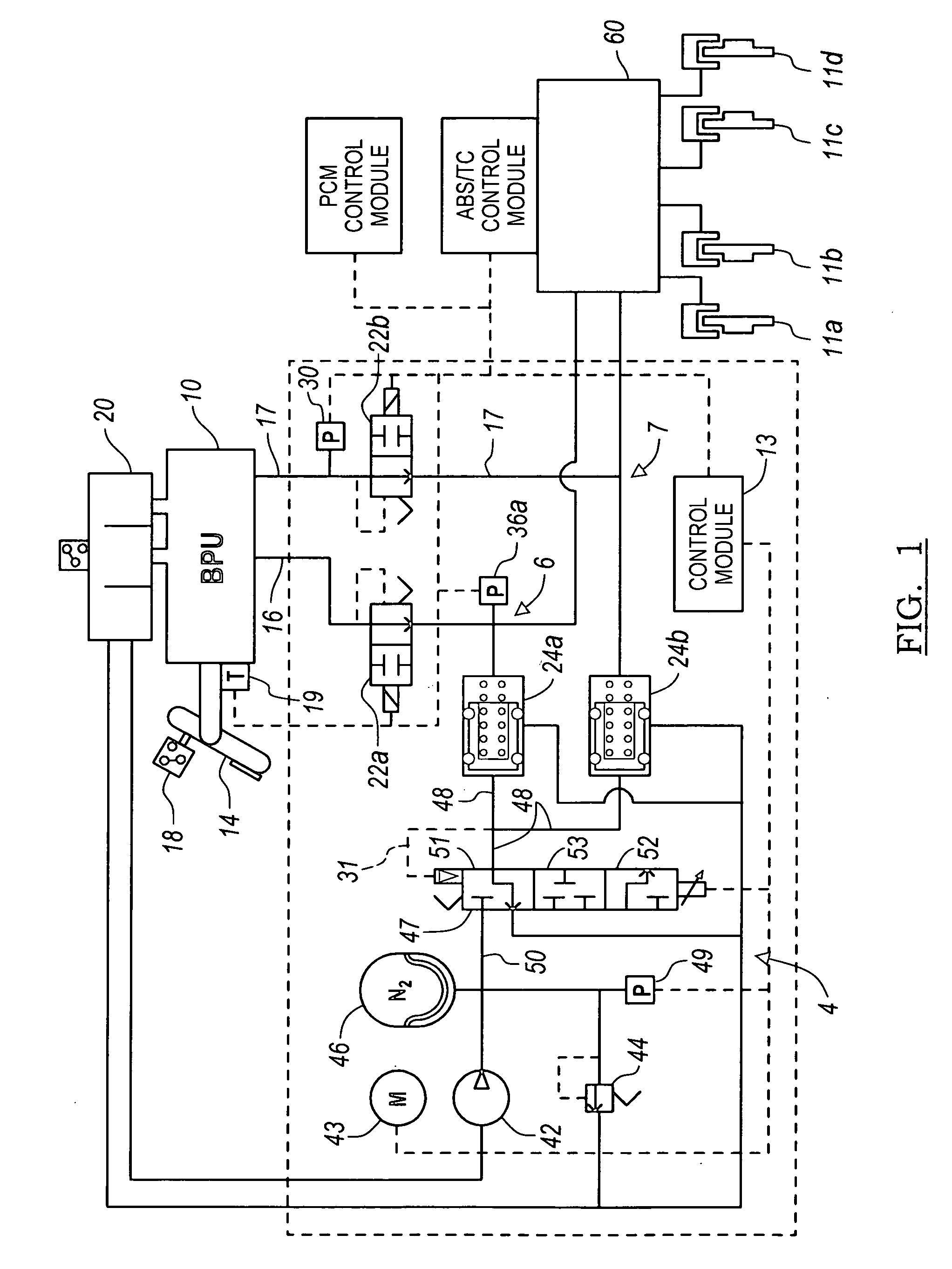
[0018] There is shown in FIG. 1, a first embodiment of a vehicle brake module indicated generally at 2, in accordance with the invention. The brake module 2 may suitably be used on a ground vehicle such as an automotive vehicle having four wheels and a brake for each wheel. Furthermore, the brake module 2 may be utilized in coordination with regenerative braking operations. Since electromagnetic force of an electric motor / generator is used in regenerative braking for providing a portion of the braking torque to the vehicle, the braking module 2 must be used in coordination with the regenerative braking portion in applying a remaining amount of brake torque, if necessary, to meet the braking needs of the vehicle. Furthermore, the brake module 2 must cooperate with other types of braking modules of the vehicle such as anti-lock braking and other traction or slip control features to effectively brake the vehicle while simulating a normal response and pedal feel to the operator of the v...


PUM


Abstract

A brake module provides a first circuit, a second circuit, and a third circuit of pressurized brake fluid. A first set and second set of brake actuators are operated by the application of pressurized brake fluid. A first and second fluid separator unit are integrated between the first and second circuit, and the first and third circuit, respectively, for substantially preventing any intermixing of pressurized brake fluid between the first, second, and third circuits. The first and second fluid separator units include a moveable pressure boundary which enables the second circuit and third circuit of pressurized brake fluid to selectively act upon the first set and second set of brake actuators in response to the first circuit of pressurized brake fluid acting upon the first and second fluid separator units. At least one proportional valve selectively controls the pressurized brake fluid of the first circuit for acting on the first and the second fluid separator units.

Description

CROSS REFERENCE TO RELATED APPLICATIONS [0001] Not Applicable. STATEMENT REGARDING FEDERALLY SPONSORED RESEARCH [0002] Not Applicable. BACKGROUND OF THE INVENTION [0003] 1. Field of the Invention [0004] The present invention relates in general to regenerative assisted braking, and more specifically, to a braking module for applying a remaining braking torque in addition to the regenerative braking torque [0005] 2. Description of the Related Art [0006] Electro-hydraulic braking systems with manually powered backup systems are used for actuating the vehicle brakes. The electro-hydraulic braking systems typically include three main hydraulic circuits. Two circuits include manual push through wherein isolation valves fluidically separate a manually powered master cylinder from the brake actuators. These isolation valves are ordinarily shut during normal braking mode to allow boost circuit controlled pressure to act on the hydraulic brake actuators of the manual push through circuits. As...

Claims


Application Information

Patent Timeline
Patent Type & Authority Applications(United States)
IPC IPC(8): B60T8/34B60T8/36B60T8/40
CPCB60T8/4081B60T8/3655
Inventor GANZEL, BLAISE
Owner KELSEY HAYES CO
Why Eureka
Try Eureka