Remote dummy load

a dummy load and remote technology, applied in the field of dummy load, can solve the problems of leds and other electronic components in the system's premature aging, and achieve the effects of reducing the number of parts required to manufacture the lamp, reducing the cost and complexity of the lamp, and facilitating installation, removal or replacemen

Active Publication Date: 2007-09-11
GE LIGHTING SOLUTIONS LLC
View PDF12 Cites 17 Cited by
  • Summary
  • Abstract
  • Description
  • Claims
  • Application Information

AI Technical Summary

Benefits of technology

[0008]The invention provides an off-lamp dummy load that minimizes the impact of heating. The inventive dummy load configuration reduces assembly cost, complexity and the number of parts associated with dummy load production. Further, the inventive dummy load provides the customer with the ability to field-modify the traffic signal.
[0010]There are several advantages to the inventive dummy load. There is no thermal path back to the LED board. The dummy load may be easily installed, removed, or replaced. The dummy load can be retrofit to adapt to a new controller, either by adding or replacing the dummy load after initial installation or by removing the dummy load, all without having to breach the sealed lamp. The number of parts required to manufacture the lamp is reduced which reduces the cost and complexity of the lamp.

Problems solved by technology

This approach creates additional heat in the system, which can cause premature aging of the LEDs and other electronic components in the system.

Method used


Image

  • Remote dummy load
  • Remote dummy load
  • Remote dummy load

Examples


Embodiment Construction

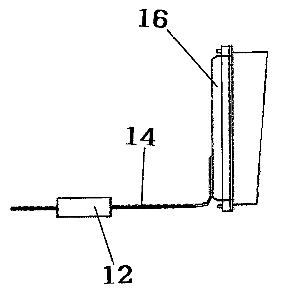
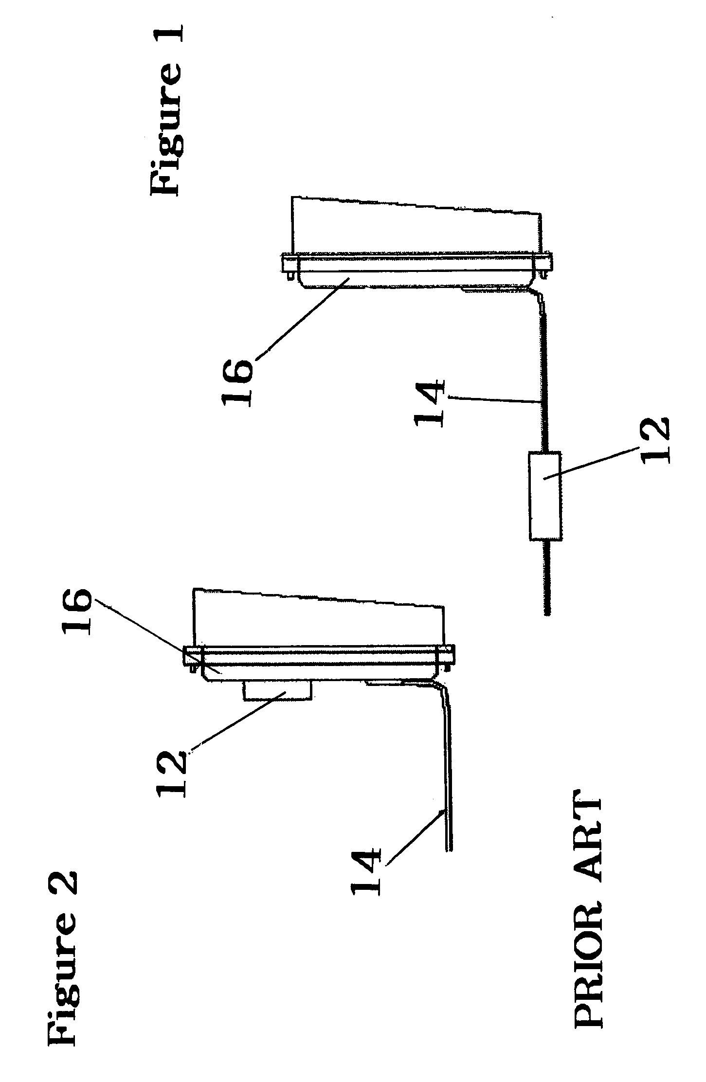
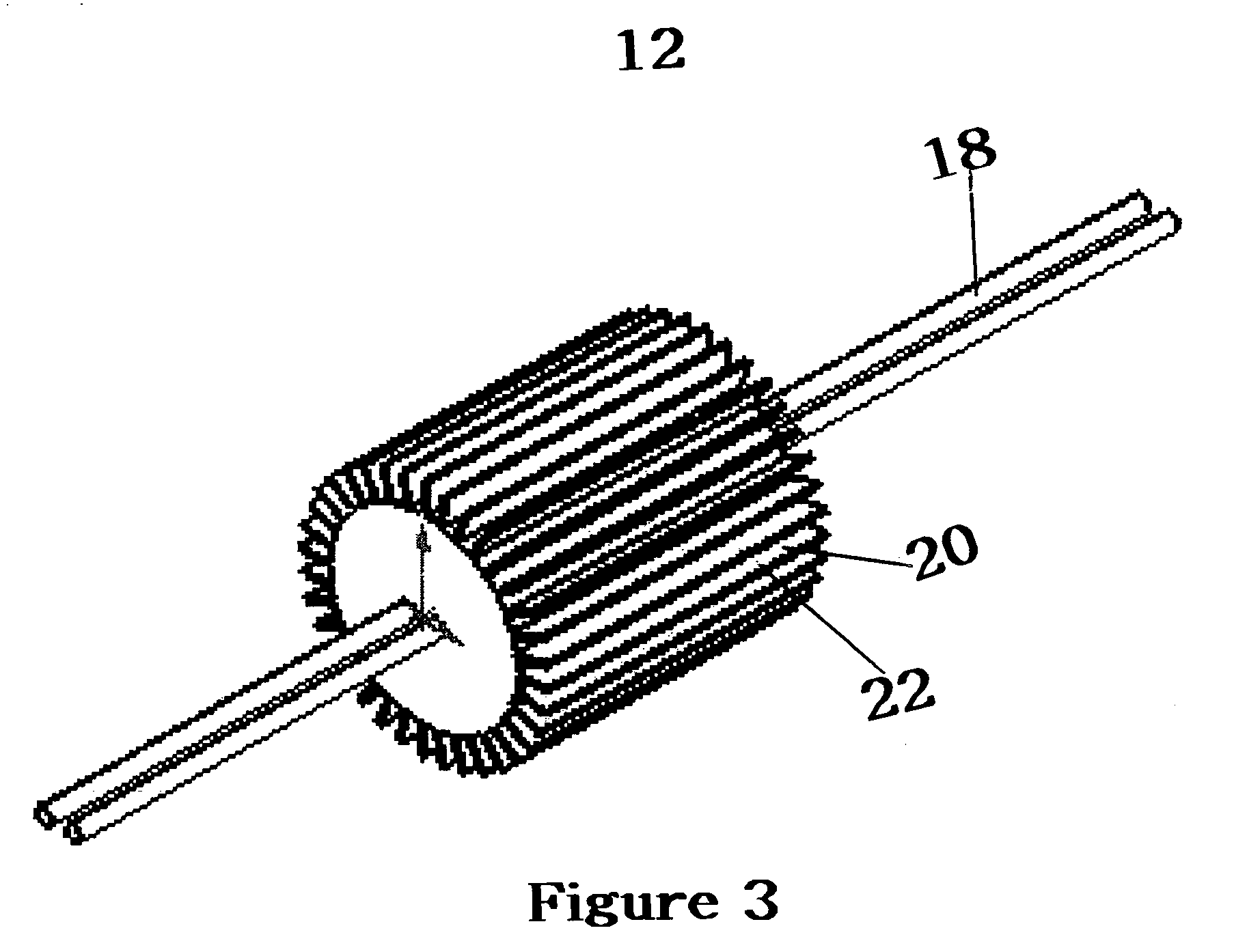
[0015]This invention relates to adding loads, preferably resistive or capacitive loads, to light emitting diode (LED) traffic signals to make them compatible with existing traffic signal controllers which were designed to work with higher power consumption incandescent light sources. For safety reasons, it is critical that a controller be able to control the LED lights signal.

[0016]Existing incandescent traffic signal controllers have minimum power load requirements. When the power load is above the minimum level, the controller recognizes that there is a signal on the line. Light emitting diode (LED) traffic signals can operate at less than this threshold value. Thus, when a LED signal is retrofit into an existing signal with a controller developed for an incandescent lamp, there must be an artificial means of creating the additional load so that the controller will recognize there is a signal on the line.

[0017]Dummy loads are often added to an existing traffic signal in the situat...


PUM


Abstract

The inventive dummy load is mounted on the input power cables of a traffic signal while managing the heat load generated by either a resistive and / or capacitive load. Using the inventive dummy load, there is no thermal path back to the light emitting diode (LED) board. The inventive dummy load may be easly installed, removed, or replaced. The dummy load can be retrofit to adapt to a new controller, either by adding to or replacing the dummy load after initial installation or by removing part or all of the dummy load. There is no need to breach the sealed lamp to adjust the dummy load. Thus, field-adjustments can be made. Further, the number of parts required to manufacture lamps for a variety of retrofit applications are reduced, which in turn reduces the cost and complexity of the lamp.

Description

BACKGROUND OF THE INVENTION[0001]1. Field of the Invention[0002]This invention relates to impedance “dummy” loads for light emitting diode (LED) traffic signals. More specifically, it relates to adding in-line resistive or capacitive loads to LED traffic signals to make them compatible with traffic signal controllers that were designed to work with higher power consumption incandescent light sources.[0003]2. Description of Related Art[0004]Existing incandecant traffic signal controllers have minimum power load requirements. When the power load is above the minimum level, the controller recognizes that there is a signal on the line. Light emitting diode (LED) traffic signals can operate at less than this threshold value. Thus, when a LED signal is retrofit into an existing signal with a controller developed for an incandecsant lamp, there must be an artificial means of creating the additional load to meet this minimum threshold value.[0005]In prior art LED signals, a resistive load i...

Claims


Application Information

Patent Timeline
Patent Type & Authority Patents(United States)
IPC IPC(8): B60R25/10G08G1/095H05B44/00
CPCG08G1/095H05B33/0884H05B45/56
Inventor BOHLER, CHRISTOPHER L.BRUNET, LOUIS
Owner GE LIGHTING SOLUTIONS LLC
Why Eureka
Try Eureka