Liquid crystal display apparatus

a technology of liquid crystal display and display screen, which is applied in the field of liquid crystal display screen, can solve the problems that the background technology of the present does not meet the three requirements, and achieve the effects of reducing the quantity of light, expanding the dynamic range and gamut, and reducing the blur of moving images

Active Publication Date: 2005-10-20
PANASONIC LIQUID CRYSTAL DISPLAY CO LTD +1
View PDF11 Cites 219 Cited by
  • Summary
  • Abstract
  • Description
  • Claims
  • Application Information

AI Technical Summary

Benefits of technology

[0020] The LCD apparatus according to the present invention is arranged to change display data of each color of the LCD and a quantity of each color ray of light emitted from the backlight unit at a time, based on the output signal sent from the light sensor for sensing light emission of the backlight unit, the video signal being inputted into the LCD for displaying the corresponding image, and the output signal sent from the ambient light sensor for sensing external ambient light. This change and control thus reduces the quantity of light of an unnecessary color emitted from the backlight unit, thereby being able to substantially expand the dynamic range and gamut and reduce a blur of a moving image. Hence, the LCD apparatus may offer a liquid crystal TV or a liquid crystal monitor which provides a capability of keeping high quality for any kind of image contents in any kind of lighting environment.

Problems solved by technology

That is, the foregoing background technologies do not meet the three respects of (1) a wide dynamic range for a well-modulated image, (2) so wide color gamut as outputting vivid colors and (3) a vivid image with no blur of a moving image, for the purpose of displaying a high-quality and visibly beautiful image on the liquid crystal TV.

Method used


Image

  • Liquid crystal display apparatus
  • Liquid crystal display apparatus
  • Liquid crystal display apparatus

Examples


first embodiment

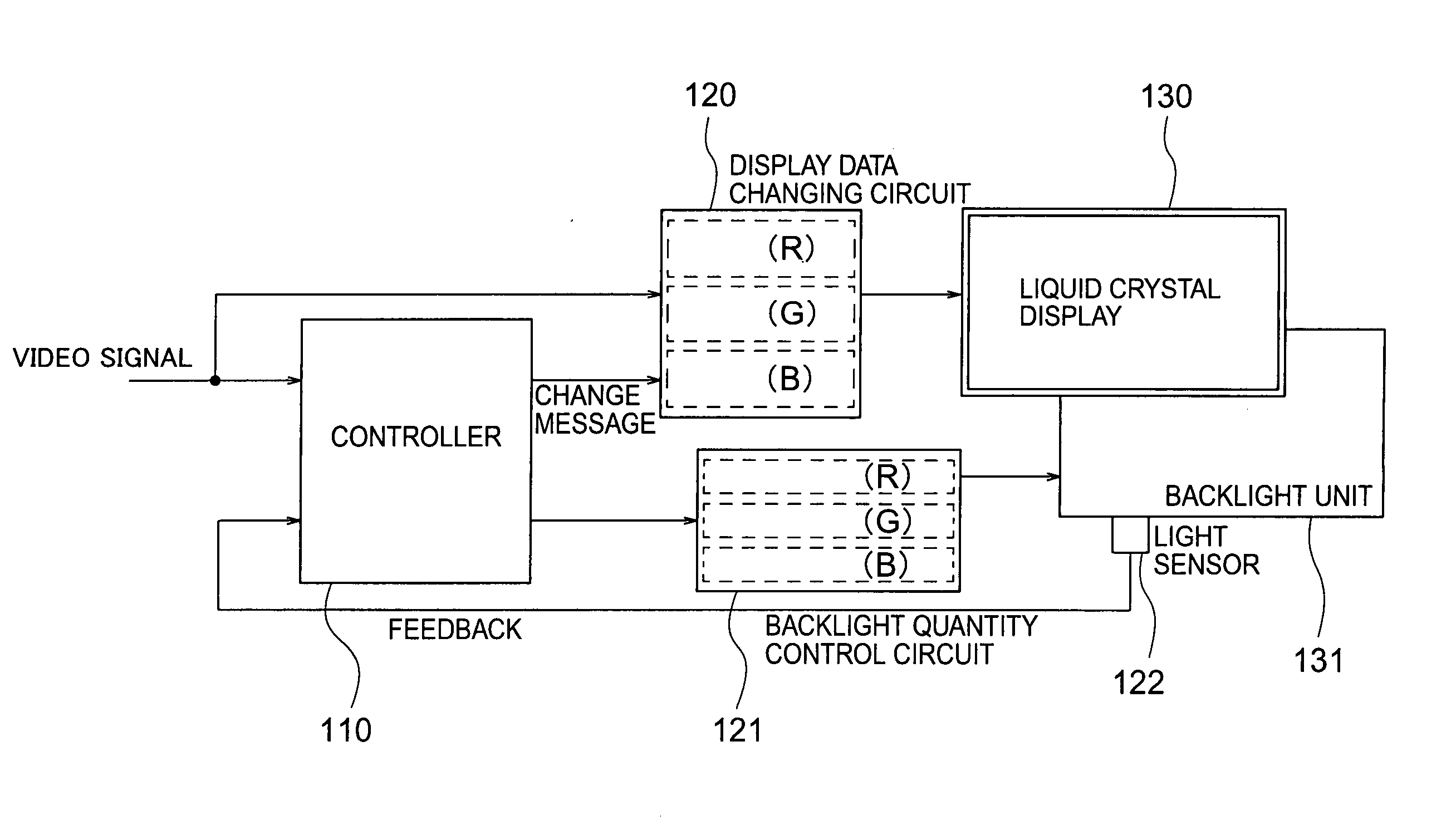
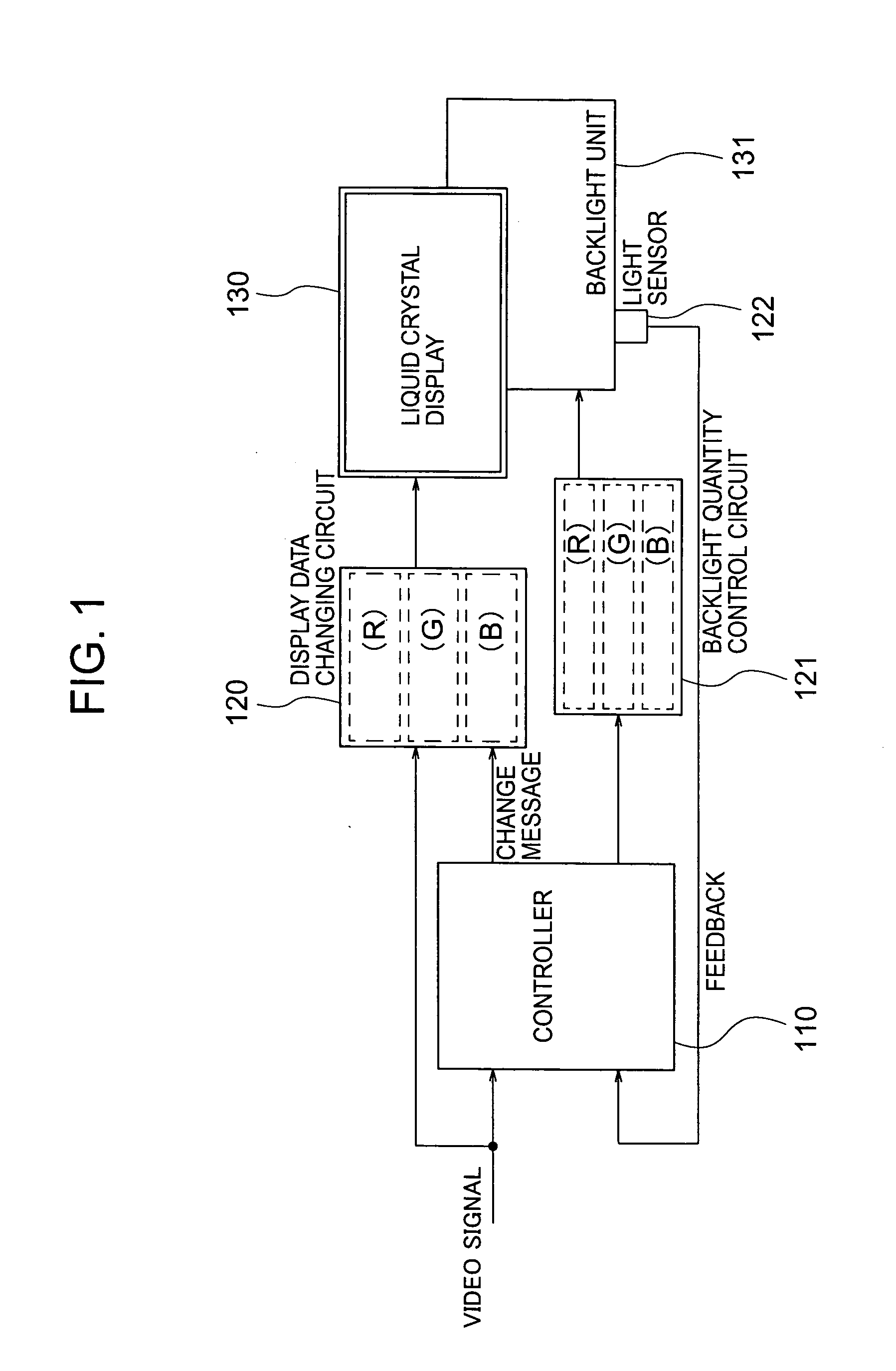
[0055]FIG. 1 is a block diagram showing an LCD apparatus according to the first embodiment of the present invention. The LCD apparatus includes a controller 110, a display data changing circuit 120, a backlight quantity control circuit 121, a LCD (liquid crystal display) 130, a backlight unit 131, and a backlight sensor 122. Though not shown in FIG. 1, like the prior art, the LCD includes a pair of substrates, a liquid crystal layer laid between the pair of substrates, a plurality of electrode groups for applying an electric field onto the liquid crystal layer, and a plurality of active elements being connected with these electrode groups. The LCD has the sub-pixel structures of three or more colors.

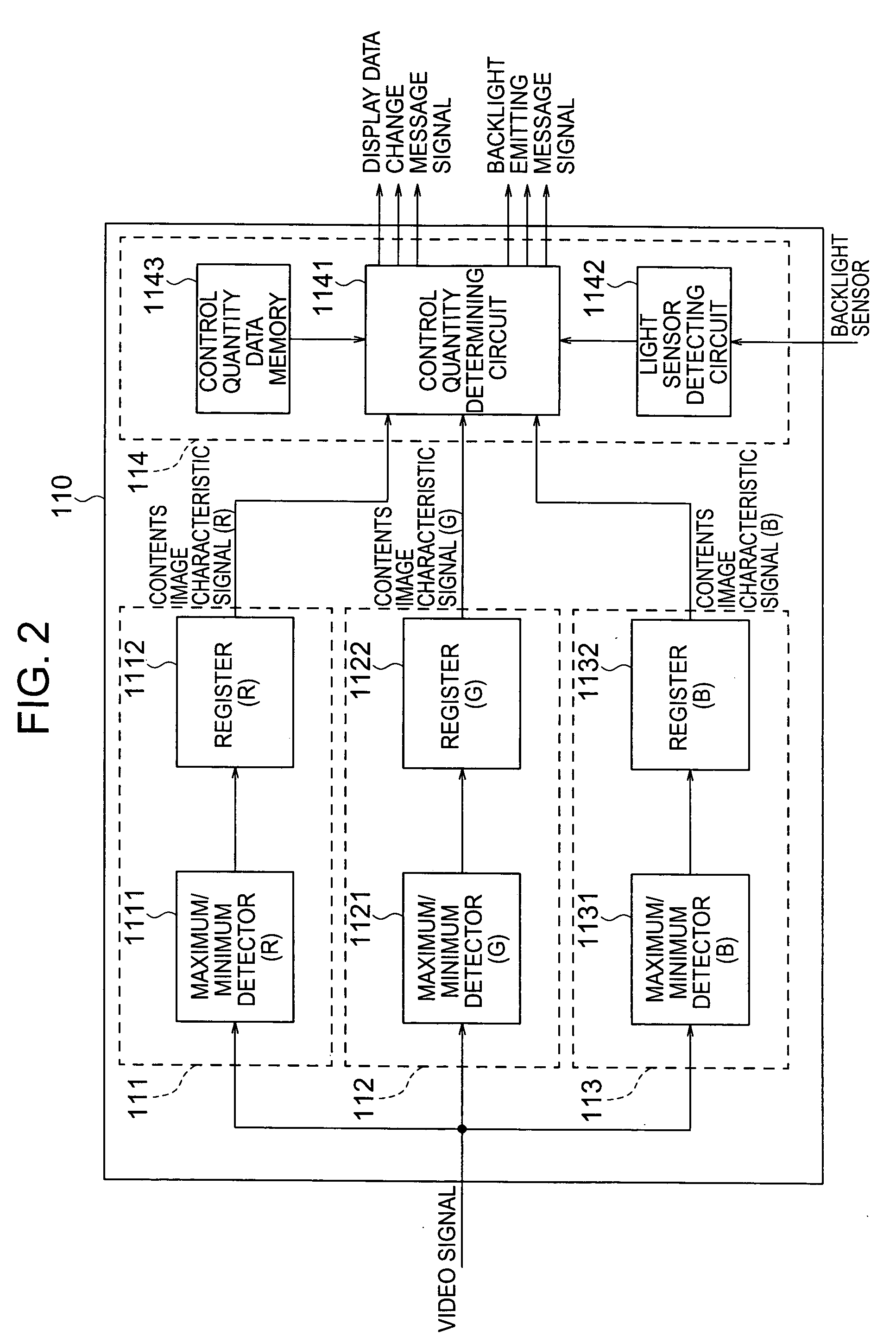
[0056] The controller 110 determines a quantity of a change of a video signal being inputted thereto and a backlight quantity at a time, based on a video signal being inputted from a personal computer or a TV tuner and a signal sent from the backlight sensor 122 for measuring a luminanc...

second embodiment

[0101]FIG. 13 is a block diagram showing the LCD apparatus according to the second embodiment. The different respect of this embodiment from the first embodiment is that a signal sent from an ambient light sensor 123 for sensing a lighting state of the environment around the LCD apparatus is inputted into the LCD apparatus in addition to the image signal to be displayed as information to be inputted into the controller 110 and the signal sent from the light sensor 122.

[0102] The internal block diagram of a controller 110 included in this embodiment is shown in FIG. 14. The different respect of FIG. 14 from FIG. 2 is that a backlight sensor detecting circuit 1144 being inputted with a signal from the light sensor 122 and an ambient light sensor detecting circuit 1145 being inputted with a signal from the ambient light sensor 123 are located in the image quality controller 114 and the signals from the two light sensors are connected with each other.

[0103] As the environments where a...

third embodiment

[0109] This embodiment is the same as the first embodiment except the following respects. In this embodiment, the VA system liquid crystal is used for the LCD 130. In the VA system liquid crystal, when no electric field is applied, the major axes of the liquid crystal molecules are aligned perpendicularly to the substrate and are not oriented in a specific direction on the plane. Hence, for displaying a black image, the polarizing axes of the upper and the lower diffusers having a liquid crystal layer laid therebetween are merely crossed with each other at right angles. That is, it is not necessary to match the angles of the liquid crystal layer to that of the diffusers with accuracy. Hence, the VA system liquid crystal is allowed to lower its transmittance of a black color as compared with any other system liquid crystal.

[0110] The lower transmittance in black display makes it possible to reduce light leakage in the display of a sole color of red, green and blue. This results in e...


PUM

PropertyMeasurementUnit
response timeaaaaaaaaaa
electric fieldaaaaaaaaaa

Abstract

The liquid crystal display apparatus includes a liquid crystal display, a backlight unit for emitting rays of light of three or more colors, the ray of each color being controlled, and applying these rays of light onto the liquid crystal display. A controller is further provided for controlling a change of display data of each color of the liquid crystal display and an emitted light quantity of each color of the backlight unit at a time, based on a video signal being inputted for displaying the corresponding image and an output signal sent from an ambient light sensor for sensing ambient light.

Description

BACKGROUND OF THE INVENTION [0001] 1. Field of the Invention [0002] The present invention relates to a liquid crystal display apparatus which offers high display quality. [0003] 2. Description of the Related Art [0004] The conventional liquid crystal display apparatus will be described below. [0005] A CRT (Cathode Ray Tube) type has been heretofore on the main stream of a display apparatus. Today, however, this stream is oriented to an active matrix type LCD (Liquid Crystal Display) apparatus. This LCD is a display apparatus that utilizes light transmittance involved in liquid crystal materials without providing no light-emitting capability. It displays an image by passing through or cutting off light emitted from a backlight unit located on the rear surface of the liquid crystal material [0006] Heretofore, a fluorescent tube has been mainly used as the backlight unit of the LCD apparatus. Today, it is reported that an LED (Light-emitting Diode) is used as the backlight unit of the ...

Claims


Application Information

Patent Timeline
Patent Type & Authority Applications(United States)
IPC IPC(8): G02F1/13357G02F1/133G09G3/20G09G3/34G09G3/36H04N5/66
CPCG02F2001/133601G09G2360/16G09G2300/0491G09G2310/0235G09G2320/0247G09G2320/0257G09G2320/0261G09G2320/0276G09G2320/0626G09G2320/064G09G2320/0653G09G2320/103G09G2360/144G09G2360/145G09G3/3413G02F1/133601G02F1/133G09G3/36
Inventor YAMAMOTO, TSUNENORIKAJITA, DAISUKEHIYAMA, IKUOKONNO, AKITOYOINUZUKA, TATSUKIWAKAGI, MASATOSHI
Owner PANASONIC LIQUID CRYSTAL DISPLAY CO LTD
Why Eureka
Try Eureka