
Liquid crystal display device, method of manufacturing the same, and electronic apparatus

a technology of liquid crystal display and liquid crystal, which is applied in the direction of optics, instruments, electrical equipment, etc., can solve the problems of reducing response speed, generating color irregularities and after images, narrow viewing angle in transmissive display mode, etc., and achieves wide viewing angle, easy and short manufacturing process, and wide viewing angle

Inactive Publication Date: 2005-10-20
SEIKO EPSON CORP
View PDF17 Cites 15 Cited by
  • Summary
  • Abstract
  • Description
  • Claims
  • Application Information

AI Technical Summary

Benefits of technology

[0007] In active matrix liquid crystal display devices that includes switching elements such as thin film diodes (TFDs) or thin film transistors (TFTs), the counter electrode normally need not be greatly processed. Particularly when the switching elements are TFTs, the counter electrode is an integral layer that need not be greatly processed (etched, for example) beyond its formation. If the configuration of Japanese Unexamined Patent Application Publication No. 2002-202511 were used for an active matrix device, then special processes would need to be performed to provide the concave portions in the counter electrode. This would result in an increase in Takt time and a raise in manufacturing costs.
[0027] An electronic apparatus of the present invention has the liquid crystal display device according to the aspect of the present invention. According to this structure, it is possible to realize an electronic apparatus having a liquid crystal display device having a wide viewing angle, high response speed, and no defect in display.

Problems solved by technology

A transflective liquid crystal display device has a problem in that a viewing angle is narrow in a transmissive display mode.
This is because there is a restriction that a reflective display must be performed using only one polarizing plate provided on the observer side since a transflective plate is provided on the inner surface of liquid crystal cells so that parallax is not generated, which results in a low degree of freedom on optical design.
This positional deviation would have a bad effect on the alignment of liquid crystal and causes a defect in arrangement, which results in the generation of color irregularity and an after image and the lowering of a response speed.
This would result in an increase in Takt time and a raise in manufacturing costs.

Method used


Image

  • Liquid crystal display device, method of manufacturing the same, and electronic apparatus
  • Liquid crystal display device, method of manufacturing the same, and electronic apparatus
  • Liquid crystal display device, method of manufacturing the same, and electronic apparatus

Examples


first embodiment

[0045] Hereinafter, the present invention will be described with reference to FIGS. 1 to 4.

[0046] An active matrix liquid crystal display device using thin film diodes (hereinafter, abbreviated to as TFDs) as pixel switching elements, particularly, a transmissive liquid crystal display device capable of performing transmissive display is taken as an example of a liquid crystal display device according to the present embodiment. In addition, in order to make each layer and each member recognizable in the drawings, each layer and each member have different reduced scales.

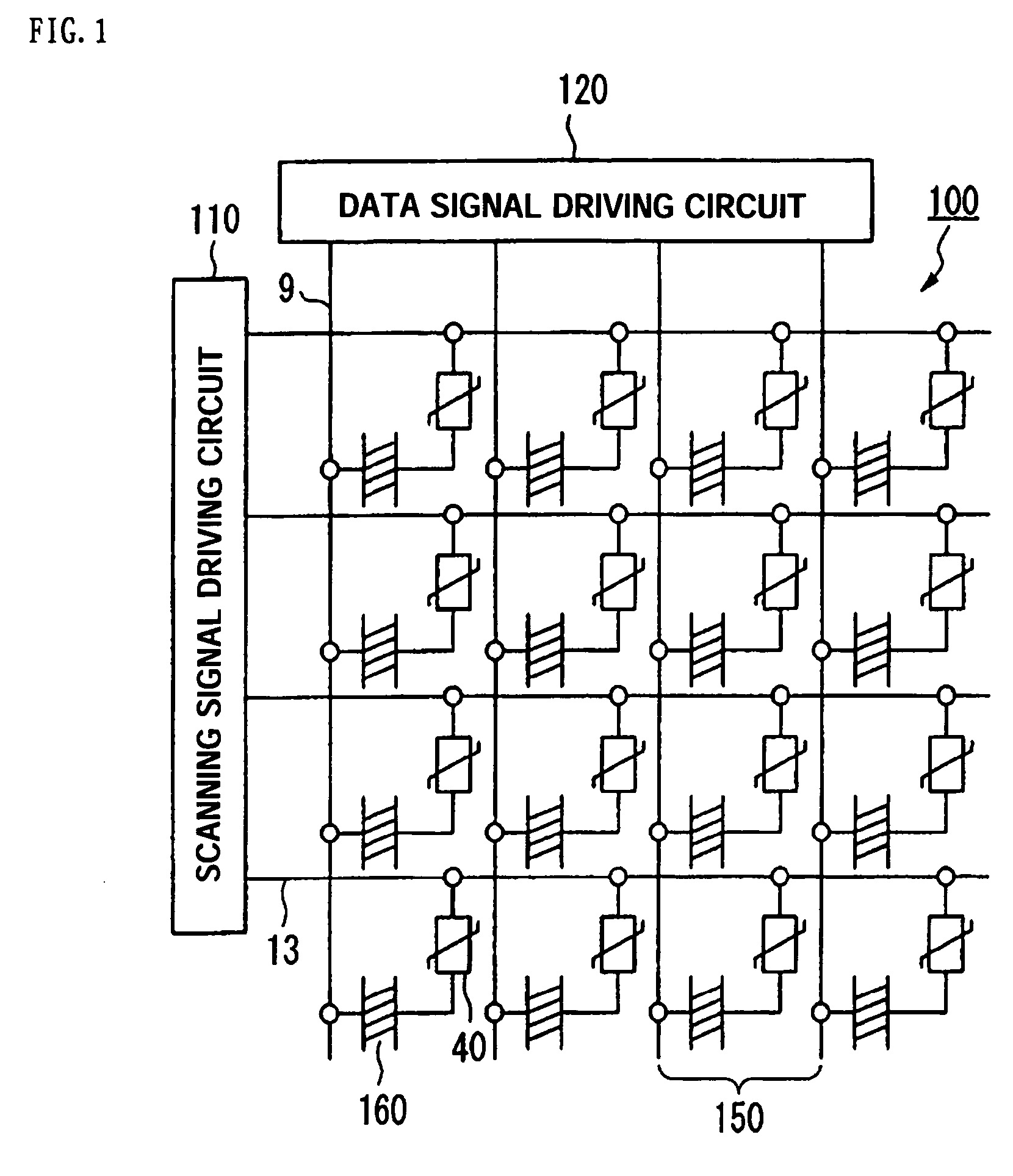
[0047]FIG. 1 shows an equivalent circuit diagram of a liquid crystal display device 100 according to the present embodiment. The liquid crystal display device 100 includes a scanning signal driving circuit 110 and a data signal driving circuit 120. The liquid crystal display device 100 is provided with signal lines, that is, a plurality of scanning lines 13 and a plurality of data lines 9 intersecting the scanning li...

second embodiment

[0065] Hereinafter, the present invention will be described with reference to FIGS. 5 and 6.

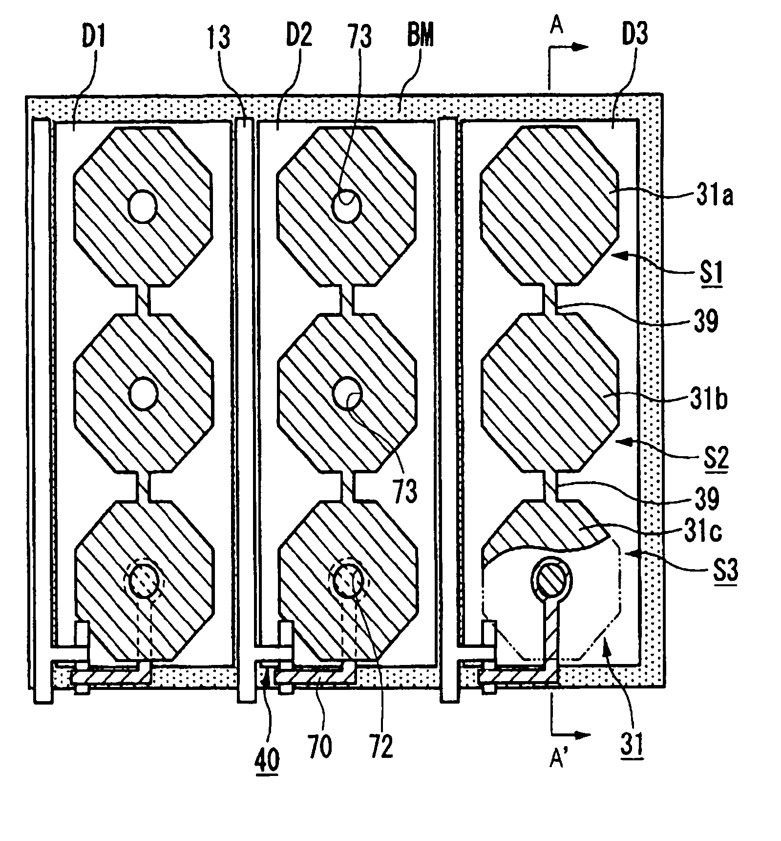
[0066]FIG. 5 is a plan view of one pixel of a liquid crystal display device according to the present embodiment and corresponds to FIG. 3 of the first embodiment. FIG. 6 is a cross-sectional view taken along the line A-A′ of FIG. 5 and corresponds to FIG. 4 of the first embodiment. The basic structure of the liquid crystal display device according to the present embodiment is the same as that in the first embodiment except for the number of divided sub-dots regions and the shape of the concave portion for alignment control. Therefore, in FIGS. 5 and 6, the same components as those in FIGS. 3 and 4 have the same reference numerals, and a detailed description thereof will be omitted.

[0067] In the first embodiment, one dot region is divided into three sub-dots regions, and the circular concave portions for alignment control and the contact holes are formed at the centers of the respective sub-d...

third embodiment

[0070] Hereinafter, the present invention will be described with reference to FIGS. 7 and 8.

[0071]FIG. 7 is a plan view of one pixel of a liquid crystal display device according to the present embodiment and corresponds to FIG. 3 of the first embodiment. FIG. 8 is a cross-sectional view taken along the line A-A′ of FIG. 7 and corresponds to FIG. 4 of the first embodiment. The basic structure of the liquid crystal display device according to the present embodiment is the same as those in the first and second embodiments except that the position of the contact hole is different from that in the second embodiment. Therefore, in FIGS. 7 and 8, the same components as those in FIGS. 3 and 4 have the same reference numerals, and a detailed description thereof will be omitted.

[0072] In the second embodiment, the contact hole, serving as the concave portion for alignment control, is formed at the center of one of two sub-dot regions. However, in the liquid crystal display device of the pres...


PUM

PropertyMeasurementUnit
depthaaaaaaaaaa
angleaaaaaaaaaa
angleaaaaaaaaaa

Abstract

A liquid crystal display device with liquid crystal in a vertical alignment mode. A pixel electrode 31 has a plurality of island-shaped portions 31a, 31b, and 31c and connecting portions 39 for connecting the plurality of island-shaped portions in each dot region. At the centers of sub-dot regions S1, S2, and S3 respectively composed of the island-shaped portions, concave portions are formed in an interlayer insulating film on a lower substrate, and the pixel electrodes are provided along inner surfaces of the concave portions in the interlayer insulating film, thereby forming concave portions 73 for alignment control. One of the plurality of concave portions 73 also serves as a contact hole 72 in each dot region.

Description

TECHNICAL FIELD [0001] The present invention relates to liquid crystal display devices having homeotropic liquid crystal. BACKGROUND ART [0002] A transflective liquid crystal display device has a problem in that a viewing angle is narrow in a transmissive display mode. This is because there is a restriction that a reflective display must be performed using only one polarizing plate provided on the observer side since a transflective plate is provided on the inner surface of liquid crystal cells so that parallax is not generated, which results in a low degree of freedom on optical design. [0003] Japanese Unexamined Patent Application Publication No. 2002-202511 discloses a transmissive liquid crystal display device adopting the vertical alignment mode. Each pixel is divided into a plurality of sub-pixels to divide one pixel into multi-domains. The shape of the sub-pixel is rotationally symmetric (for example, a substantially circular shape, a substantially rectangular shape, or a sub...

Claims


Application Information

Patent Timeline
Patent Type & Authority Applications(United States)
IPC IPC(8): G02F1/1333G02F1/1365G02F1/1335G02F1/1343G02F1/1362H01L49/02
CPCG02F1/133555G02F1/136227G02F1/133707
Inventor NISHIMURA, JOJI
Owner SEIKO EPSON CORP
Learn More