
Variable power optical system, imaging apparatus, and digital apparatus

Inactive Publication Date: 2005-10-20
KONICA MINOLTA OPTO
View PDF4 Cites 12 Cited by
  • Summary
  • Abstract
  • Description
  • Claims
  • Application Information

AI Technical Summary

Benefits of technology

[0011] The present invention mainly aims to provide a variable power optical system in which error sensitivity of the lens group is low and adjustment between lenses is easy.
[0012] The present invention also aims to provide a compact and inexpensive variable power optical system that responds to high pixel imaging element.
[0013] In one aspect of the present invention, in order to achieve the above aims and other aims, the variable power optical system that performs variable power by changing the distance between each lens group in an optical axis direction includes from an object side, a first lens group including a cemented lens, configured by less than or equal to three lenses, including at least one aspherical surface and having a negative optical power as a whole; and a second lens group including at least one aspherical surface and having a positive optical power as a whole, wherein the distance between the first lens group and the second lens group is narrowed when performing variable power from wide-angle end to telephoto end.
[0014] According to such configuration, the first lens group positioned closest to the object side is a so-called negative lead having a negative optical power. Thus, rays entering at a large angle from the object side are among the first to be mitigated by the negative optical power of the first lens group. In the configuration of the negative lead, increase in error sensitivity is suppressed even if the size is made small. Generally, when the first lens group is configured by one negative lens, the optical power of the first lens group cannot be made strong to suppress generation of astigmatism and chromatic aberration of magnification at the first lens group. As a result, the front cell diameter of the first lens group increases. When configured by a plurality of lenses, decentration error sensitivity in the first lens group increases when made compact in the optical axis direction, thus requiring adjustment between lenses in the first lens group.
[0015] In a configuration in which the first lens group includes the cemented lens, increase in front cell diameter is prevented, and at the same time, error sensitivity caused by decentration is reduced. Further, in a configuration in which the optical power of the lens group includes negative and positive optical power in the order from the object side, the first lens group is mainly related to off-axis aberration and the second lens group is mainly related to axial aberration. Various aberrations are each corrected by applying aspherical surface in the first lens group and the second lens group. Reduction of error sensitivity and correction of off-axis aberration are both achieved by combining the cemented lens and the aspherical lens.

Problems solved by technology

Generally, when the first lens group is configured by one negative lens, the optical power of the first lens group cannot be made strong to suppress generation of astigmatism and chromatic aberration of magnification at the first lens group.
When configured by a plurality of lenses, decentration error sensitivity in the first lens group increases when made compact in the optical axis direction, thus requiring adjustment between lenses in the first lens group.

Method used


Image

  • Variable power optical system, imaging apparatus, and digital apparatus
  • Variable power optical system, imaging apparatus, and digital apparatus
  • Variable power optical system, imaging apparatus, and digital apparatus

Examples


embodiment 1

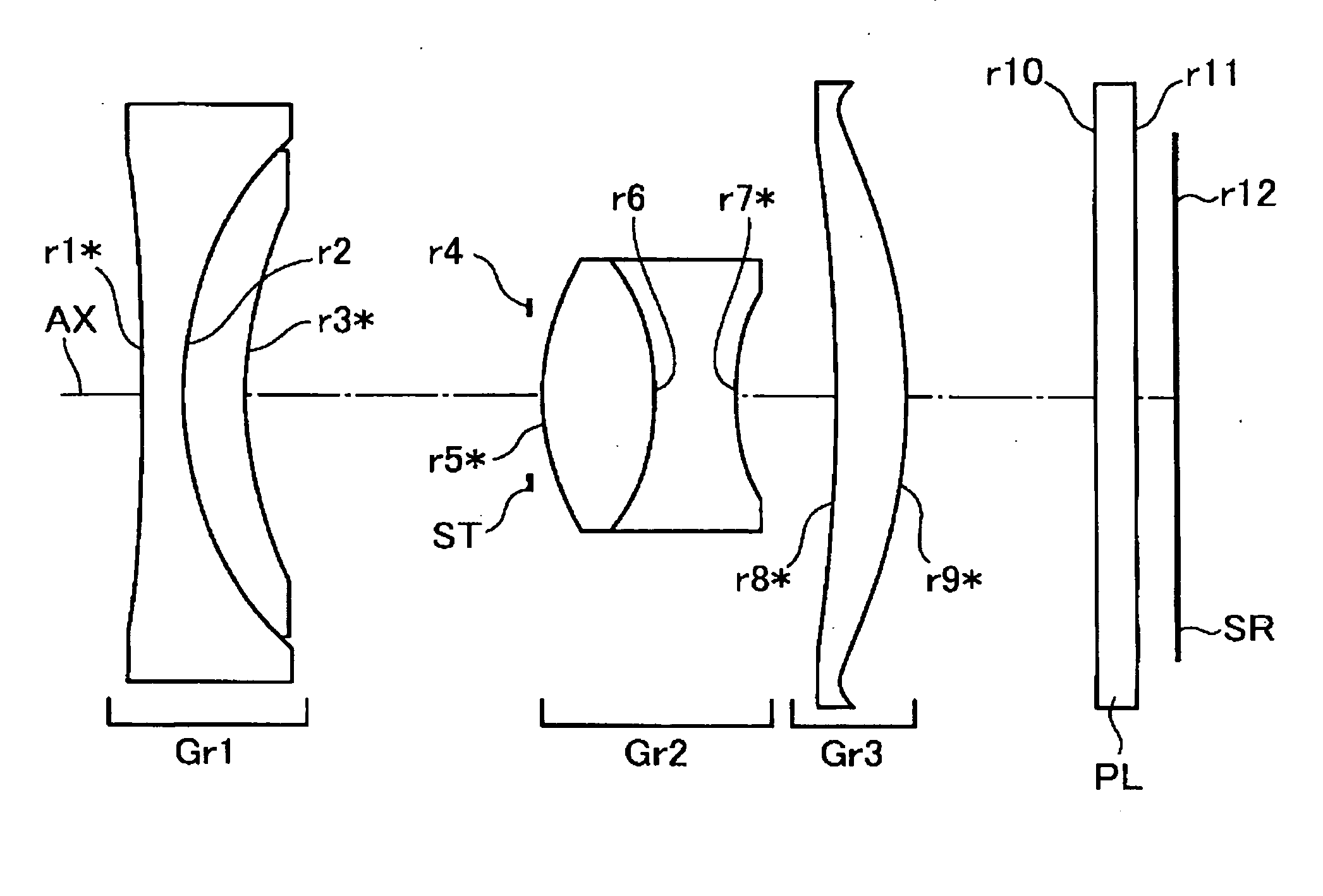
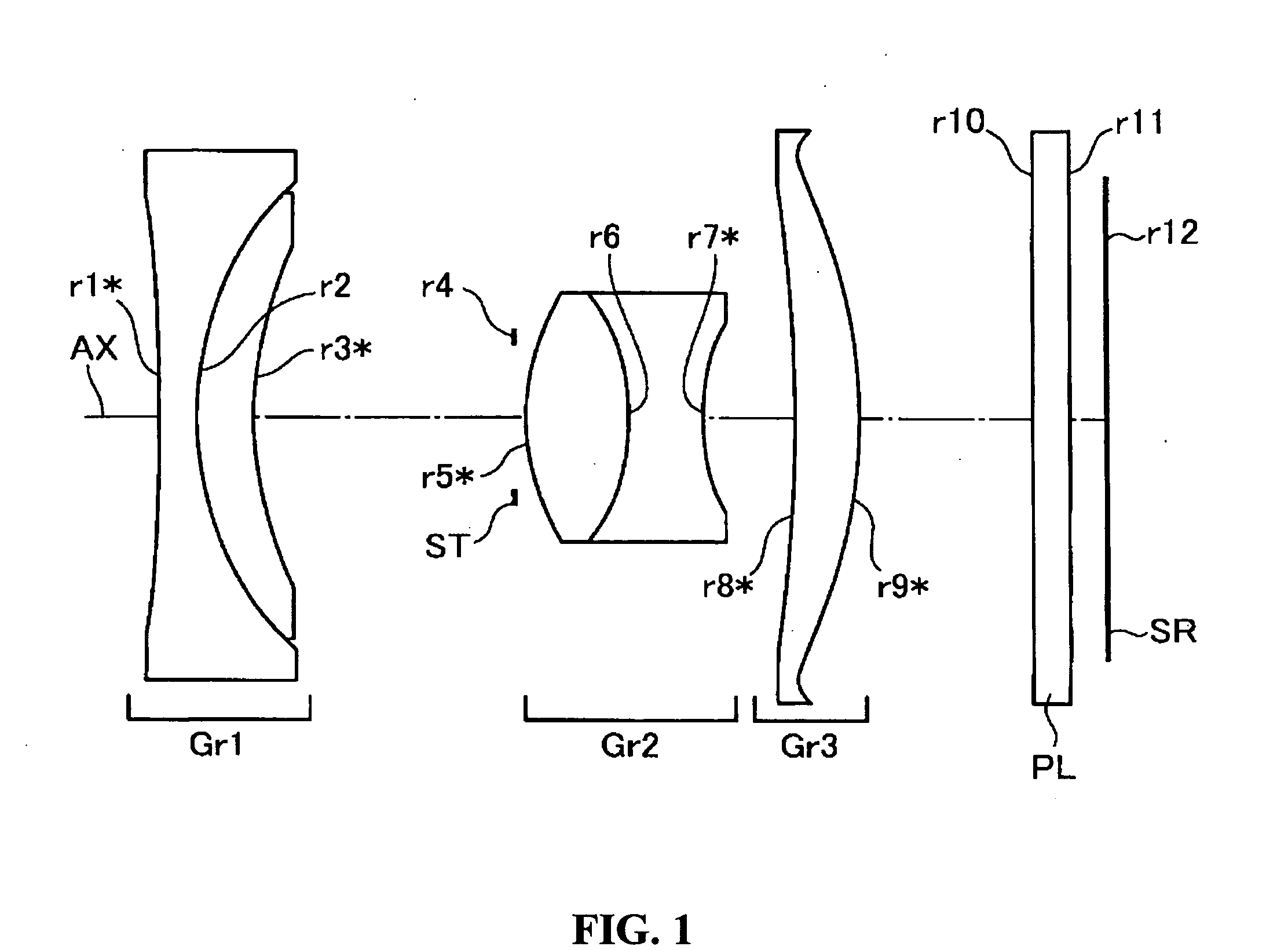
[0046]FIG. 1 is a cross sectional view longitudinally taken along the optical axis (AX) showing an arrangement of lens groups in a variable power optical system of Embodiment 1. In FIG. 1 and FIG. 2 to FIG. 7 explained below, the lens arrangement in wide-angle end (W) is shown. Embodiment 1 is configured by, in the order from the object side (left side in FIG. 1), a first lens group (Gr1) having a negative optical power as a whole, a second lens group (Gr2) having a positive optical power, and a third lens group (Gr3) having a positive optical power. Further, in each embodiment, an optical stop (ST) for adjusting the quantity of light is arranged on the first lens group (Gr1) side of the second lens group (Gr2). A parallel plane plate (PL) and an imaging element (SR) are arranged adjacent to the third lens group (Gr3) on the side away from the second lens group (Gr2) (adjacent to the fourth lens group (Gr4) on the side away from the third lens group (Gr3) in Embodiment 4).

[0047] Te...

embodiment 2

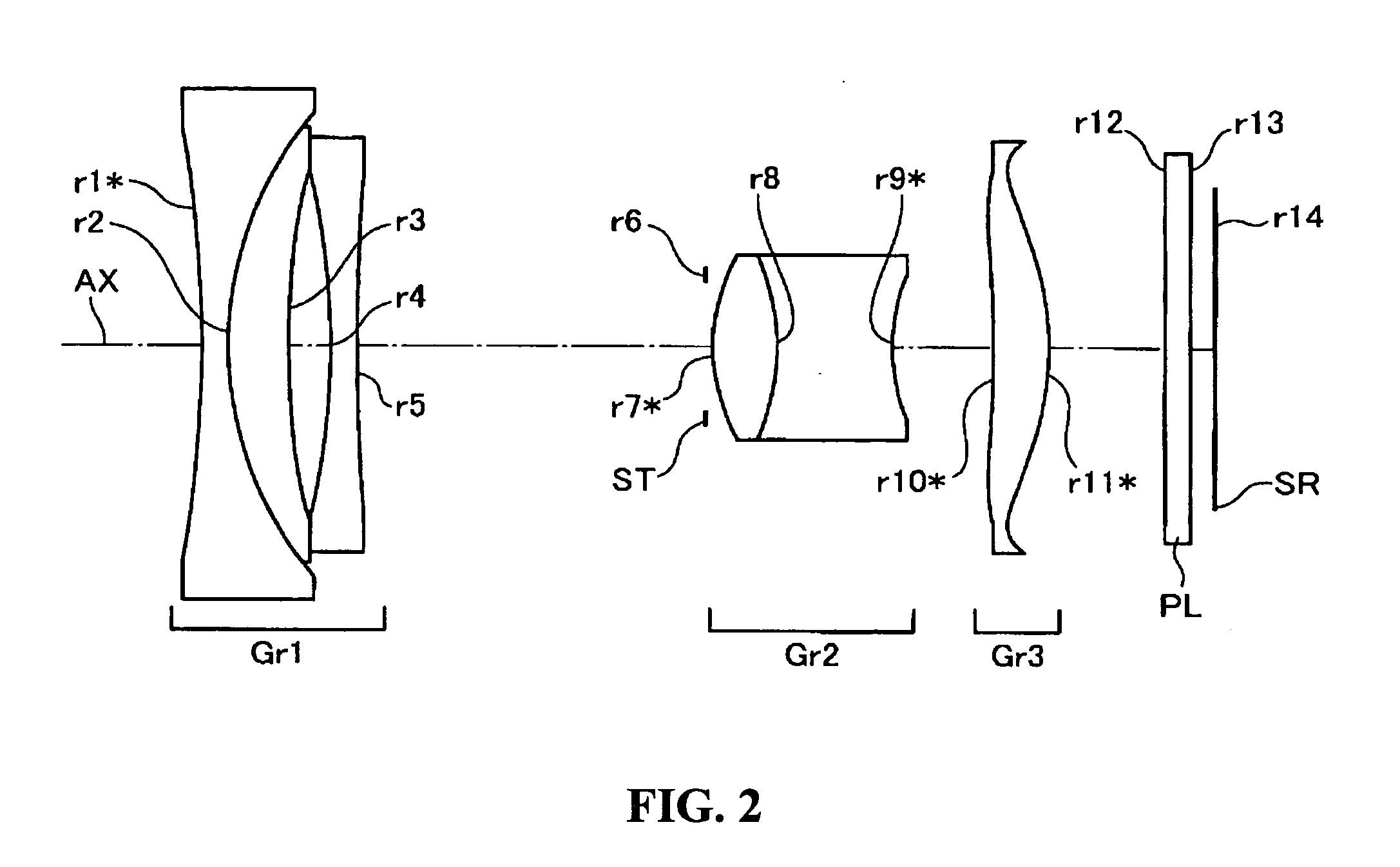
[0052]FIG. 2 is a cross sectional view longitudinally taken along the optical axis (AX) showing an arrangement of lens groups in a variable power optical system of Embodiment 2. The variable power optical system of Embodiment 2 is configured in the following way in the order from the object side. The first lens group (Gr1) having a negative optical power as a whole is configured by a cemented lens of a negative lens that is concave on both sides and a positive meniscus lens that is convex on the object side, and a negative lens that is concave on both sides. The second lens group (Gr2) having a positive optical power as a whole is a cemented lens of a positive lens that is convex on both sides and a negative lens that is concave on both sides. The third lens group (Gr3) having a positive optical power as a whole is a single positive meniscus lens that is convex on the image side.

[0053] In Embodiment 2 of such lens configuration, all of the first lens group (Gr1), the second lens gr...

embodiment 3

[0054]FIG. 3 is a cross sectional view longitudinally taken along the optical axis (AX) showing an arrangement of lens groups in a variable power optical system of Embodiment 3. The variable power optical system of Embodiment 3 shown in FIG. 3 has each lens group configured in the following way in the order from the object side. The first lens group (Gr1) having a negative optical power as a whole is a cemented lens of a negative lens that is concave on both sides, and a positive meniscus lens that is convex on the object side. The second lens group (Gr2) having a positive optical power as a whole is a cemented lens of a positive lens that is convex on both sides and a negative lens that is concave on both sides. The third lens group (Gr3) having a positive optical power as a whole is a single positive meniscus lens that is convex on the image side.

[0055] In Embodiment 3 of such lens configuration, all of the first lens group (Gr1), the second lens group (Gr2) and the third lens gr...


PUM


Abstract

A small high]-definition variable power optical system having a variable power ratio of about two to three times; an imaging apparatus including the variable power optical system; and digital equipment mounted with the imaging apparatus are provided. The variable power optical system, consisting of a plurality of lens groups, for performing variable power by changing the distance between each lens groups in an optical axis direction is configured by two or more lens groups, each having negative or positive optical power, arranged in such order from the object side. The first lens group is a cemented lens configured by at least one negative lens and at least one positive lens arranged in order from the object side. At least one aspherical surface is arranged to each of the first lens group and the second lens group. A third lens group having a positive optical power is arranged on the image plane side of the second lens group.

Description

[0001] The present application claims priority to Japanese Patent Application No. 2004-123997 filed Apr. 20, 2004, the entire content of which is hereby incorporated by reference. BACKGROUND OF THE INVENTION [0002] 1. Field of the Invention [0003] The present invention relates to a variable power optical system, consisting of a plurality of lens groups, for carrying out variable power by changing the distance between each lens group in the optical axis direction, an imaging apparatus including the variable power optical system, and a digital equipment mounted with the imaging apparatus. [0004] 2. Description of the Related Art [0005] Recently, portable telephones and personal digital assistants (PDA) are being used widespread, and the specification of having a compact digital still camera unit or a digital video camera unit built into such equipment is becoming common. In such equipment, the imaging apparatus including a small imaging element having a low pixel number compared to a ...

Claims


Application Information

Patent Timeline
IPC IPC(8): G02B15/16G02B13/00G02B13/18G02B15/14G02B15/163G02B15/177G02B15/20H04N5/225
CPCG02B13/0035G02B13/004G02B15/177G02B13/009G02B13/006G02B15/143507
Inventor MATSUSAKA, KEIJI
Owner KONICA MINOLTA OPTO
Learn More