Projection type video display

a video display and projection type technology, applied in the field of projection type video displays, can solve the problems of light leakage and high temperature of light sources, and achieve the effect of high heat radiation efficiency

Inactive Publication Date: 2005-10-20
SANYO ELECTRIC CO LTD
View PDF13 Cites 48 Cited by
  • Summary
  • Abstract
  • Description
  • Claims
  • Application Information

AI Technical Summary

Benefits of technology

[0005] In view of the foregoing circumstances, it is an object of the present invention to provide a projection type vid

Problems solved by technology

However, a light source is heated to high temperature due to generation of heat when a

Method used


Image

  • Projection type video display
  • Projection type video display
  • Projection type video display

Examples


embodiment 1

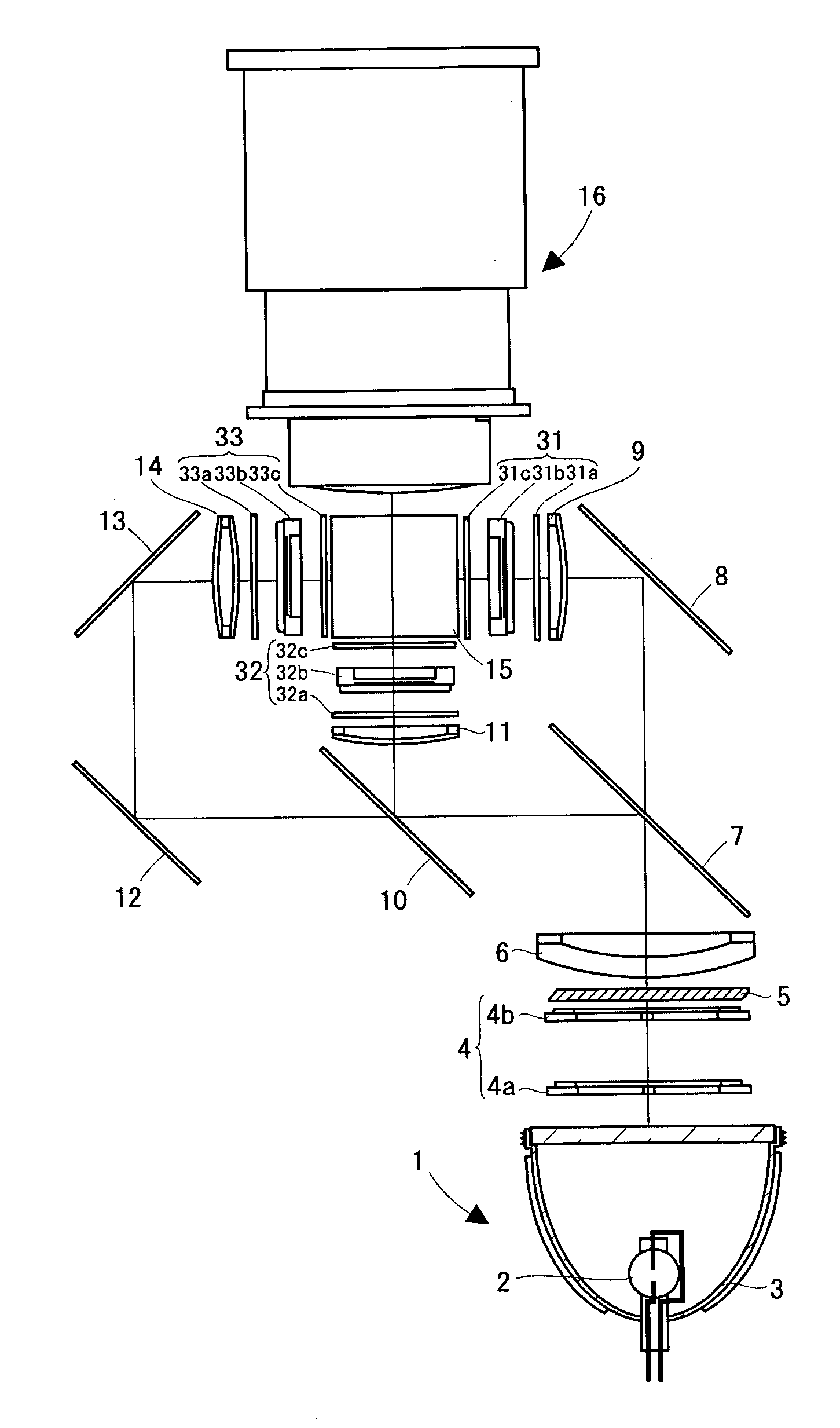
[0016] A liquid crystal projector according to the embodiment 1 of the present invention is now described referring to FIG. 1 and FIG. 2.

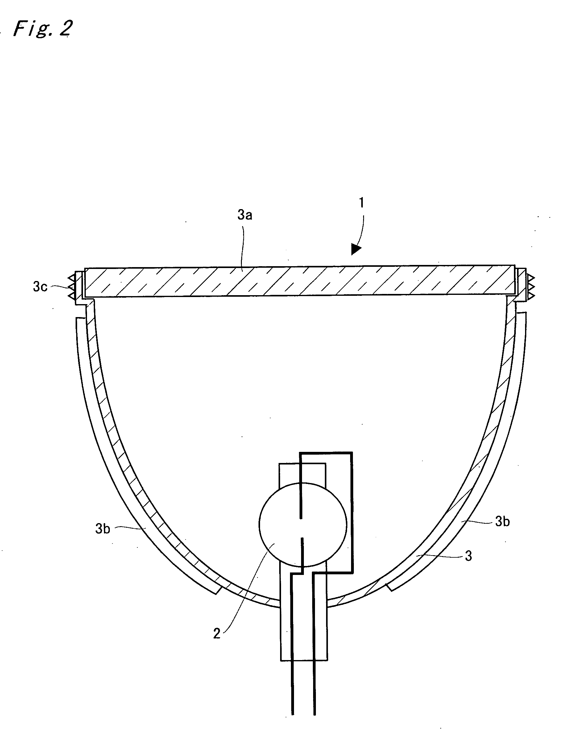
[0017]FIG. 1 shows a three-panel liquid crystal projector according to this embodiment. A light source 1 comprises a lamp 2 such as an ultra-high pressure mercury lamp or a metal halide lamp, and its irradiated light is emitted after being changed into parallel light by a parabolic reflector 3 and is guided to an integrator lens 4.

[0018] The integrator lens 4 is composed of a pair of a group of lenses (fly's eye lenses) 4a and 4b and respective lens portions guide light emitted from the lamp 2 to the whole surface of each liquid crystal light valve 31, 32 and 33 as display devices described later. Therefore, the integrator lens 4 evens off local luminance nonuniformity existing in the lamp 2, thereby decreasing the difference between the light amount at the screen center and the light amount at the screen perimeter. The light which has passed thr...

embodiment 2

[0028] A parabolic reflector 3 in Embodiment 2 is made of aluminum and its shape is made with the same processing as in Embodiment 1.

[0029] A lamp 2 containing mercury such as an ultra high pressure mercury lamp is used as a lamp 2. There is a concern that mercury vaporized by the heat of the lamp 2 will leak out of the lamp 2 and flow out from the gap of the light source 1 in case of the burst of the lamp 2.

[0030] However, aluminum has a characteristic that it reacts with mercury to form an alloy (amalgam). Therefore, vaporized mercury leaked out of the lamp 2 reacts with the parabolic reflector 3 made of aluminum to be an alloy, and then the alloy adheres to the reflecting surface of the parabolic reflector 3. As a result, there is no concern that a user will be exposed to mercury and the safety is enhanced.

[0031] In Embodiment 2, the parabolic reflector 3 itself is made of aluminum, but it does not mean that the configuration should be limited to the same. Aluminum may be coat...


PUM

PropertyMeasurementUnit
Transparencyaaaaaaaaaa

Abstract

A light source comprises a lamp such as an ultra-high pressure mercury lamp or a metal halide lamp and its irradiated light is emitted after being parallelized by a parabolic reflector. The parabolic reflector is made by pressing metal such as stainless and its light exit side aperture is covered with a transparent plate made of glass, etc. The transparent plate prevents fragments of glass of the lamp and the like from scattering when the lamp bursts. The parabolic reflector does not have an aperture (cut-out) for ventilation, but heat radiation fins are formed on the outer surface of it.

Description

BACKGROUND OF THE INVENTION [0001] Field of the Invention [0002] The present invention relates to a projection type video display such as a liquid crystal projector, and the like. [0003] A light source for a projection type video display generally comprises a lamp and a parabolic reflector. A conventional parabolic reflector is made of glass (see JP-A-2002-216531). SUMMARY OF THE INVENTION [0004] However, a light source is heated to high temperature due to generation of heat when a lamp is on. A parabolic reflector made of glass has low efficiency of heat radiation, therefore, the reflector should be provided with an aperture for ventilation in order to secure a passage for cooling air. On the other hand, in preparation for the burst of the lamp, the light source should have a structure to prevent fragments of glass of the lamp and the like from scattering. When the reflector is provided with the aperture for ventilation, it is likely that the fragments of glass of the lamp and the ...

Claims


Application Information

Patent Timeline
IPC IPC(8): G03B21/14F21V7/22F21V15/00G02F1/1335G03B21/00G03B21/16G03B21/20H04N5/74
CPCF21V7/22G03B21/2026H04N9/3141F21V7/24F21V7/28
Inventor KOBA, HIROKISHIOTSU, SHINICHITAHARA, MOTOSHITERADA, KATSUMIYAMAMOTO, HIDEKI
Owner SANYO ELECTRIC CO LTD
Why Eureka
Try Eureka