Method and apparatus for sealing an ultrahigh-pressure fluid system

a fluid system and ultra-high-pressure technology, applied in the direction of positive-displacement liquid engines, hose connections, piston pumps, etc., can solve the problems of reduced service life of seals, so as to prevent the displacement of seals

Inactive Publication Date: 2008-01-24
FLOW INT
View PDF13 Cites 33 Cited by
  • Summary
  • Abstract
  • Description
  • Claims
  • Application Information

AI Technical Summary

Benefits of technology

[0010] According to one embodiment, a sealing assembly for an ultrahigh-pressure fluid system having a plunger configured to reciprocate therein along a longitudinal axis, comprises a seal having a bore through which the plunger may reciprocate, a bearing positioned adjacent the seal and having a bore through which the plunger may reci

Problems solved by technology

For example, when various pump components, such as dynamic seals, are subjected to high pressures, up to and beyond 87,000 psi, the seals have a limited operational life.
Given the very short component life, frequent component replacement is required, resulting in down time of the machine, lo

Method used


Image

  • Method and apparatus for sealing an ultrahigh-pressure fluid system
  • Method and apparatus for sealing an ultrahigh-pressure fluid system
  • Method and apparatus for sealing an ultrahigh-pressure fluid system

Examples


Embodiment Construction

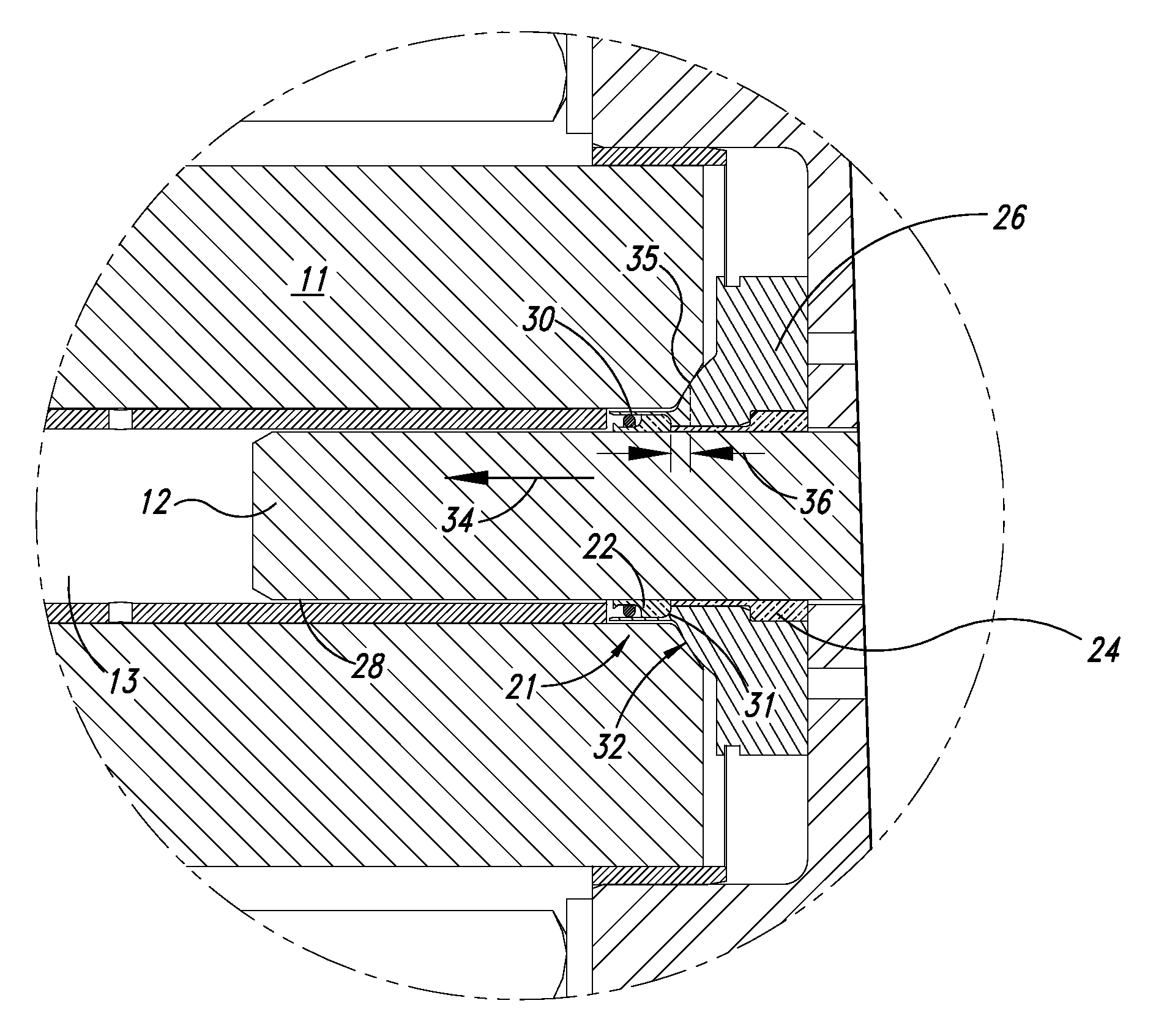
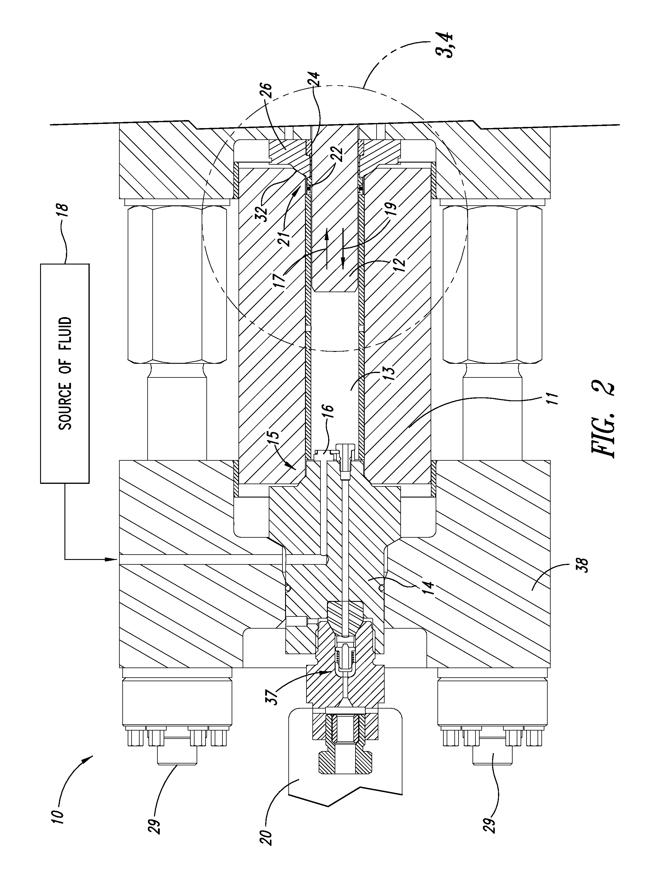
[0023] In many situations, it would be desirable to optimize an operation of ultrahigh-pressure fluid pumps at higher pressures and improve longevity of components thereof. For example, an ultrahigh-pressure intensifier pump, such as those manufactured by Flow International Corporation, may be used for a variety of applications, such as supplying high-pressure fluid to an abrasive waterjet cutting head, or pressurizing a pressure vessel to pasteurize food products. While the below discussion will use an ultrahigh-pressure intensifier as an example, it will be understood that the present invention has application in sealing an axially reciprocating plunger of any high-pressure pump.

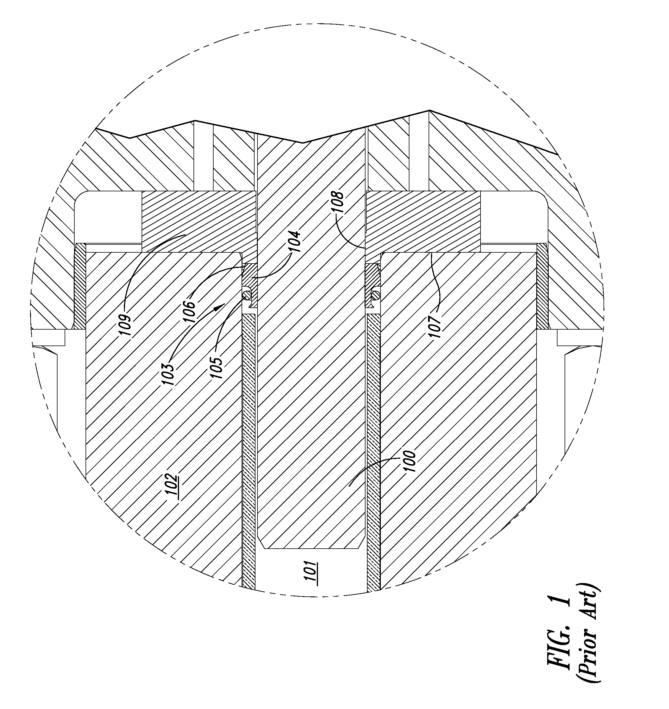
[0024] As described previously, a reciprocating plunger in an intensifier reciprocates within a bore of the pump cylinder. Fluid is maintained within a desired pressurizing region of the pump cylinder by a dynamic seal surrounding the plunger. While a variety of such dynamic seals have been used previousl...


PUM


Abstract

A seal carrier is provided for an ultrahigh-pressure fluid system having a plunger configured to reciprocate therein along a longitudinal axis when the ultra-high pressure fluid system is in operation, the seal carrier having an inner surface provided with a first portion configured to captively receive a seal, substantially preventing displacement of the seal in a direction substantially parallel to the longitudinal axis, and a second portion configured to circumferentially surround a bearing. The seal carrier is further provided with an outer surface having a recess formed along at least a portion of a circumference thereof, the recess at least partially positioned opposite the first portion of the inner surface along a lateral axis substantially perpendicular to the longitudinal axis.

Description

CROSS-REFERENCE TO RELATED APPLICATION [0001] This application is a continuation-in-part of U.S. patent application Ser. No. 10 / 423,661, entitled “Method and Apparatus for Sealing an Ultrahigh-Pressure Fluid System,” filed Apr. 25, 2003, which application is still pending and a continuation-in-part of U.S. patent application Ser. No. 10 / 038,507, entitled “Components, Systems, and Methods for Forming a Gasketless Seal Between Like Metal Components in an Ultrahigh-Pressure System,” filed Jan. 2, 2002, which application has been issued U.S. Pat. No. 6,802,541.BACKGROUND OF THE INVENTION [0002] 1. Field of the Invention [0003] The present invention relates to ultrahigh-pressure fluid systems, and in particular, to methods and assemblies for sealing ultrahigh-pressure systems, such as ultrahigh-pressure pumps. [0004] 2. Description of the Related Art [0005] High-pressure pumps and ultrahigh-pressure pumps draw a volume of fluid into the pump on an intake stroke of a plunger, and on a pre...

Claims


Application Information

Patent Timeline
IPC IPC(8): F16L35/00F04B17/00F04B53/16F16J15/04
CPCF04B53/02F16J15/56F04B53/164F04B53/162
Inventor HOPKINS, JORDAN J.HAWES, ADRIAN
Owner FLOW INT
Why Eureka
Try Eureka