Emission device for an ultra-high pressure mercury lamp

a mercury lamp and emission device technology, applied in the direction of electric variable regulation, cathode-ray/electron beam tube circuit elements, instruments, etc., can solve the problems of not always having an ideal shape and insufficient light to emerg

Active Publication Date: 2006-10-17
USHIO DENKI KK
View PDF10 Cites 34 Cited by
  • Summary
  • Abstract
  • Description
  • Claims
  • Application Information

AI Technical Summary

Benefits of technology

[0023]As was described above, in the emission device of the invention for an ultra-high pressure discharge lamp, for the half period of an alternating current immediately after polarity switching, a high pulse current is superimposed. The surface of the electrode tip area of the discharge lamp is therefore shifted into a molten state at least for each switching into operation as an anode (electrode operation as an anode). In this way, the formation of an undesirable shape, such as an asperity formation on the surface of the electrode tip area or the like can be prevented.

Problems solved by technology

However, since they form, as was described above, in the course of operation of the discharge lamp by a physical phenomenon, they do not always have an ideal shape.
Especially in the case in which they have a crooked shape, such as showing asperity, the starting point of the discharge becomes unstable, which causes the serious disadvantage that, in the case of a light source of a projector device which is designed such that a point light source is assumed, light cannot emerge to a sufficient degree.

Method used


Image

  • Emission device for an ultra-high pressure mercury lamp
  • Emission device for an ultra-high pressure mercury lamp
  • Emission device for an ultra-high pressure mercury lamp

Examples


Embodiment Construction

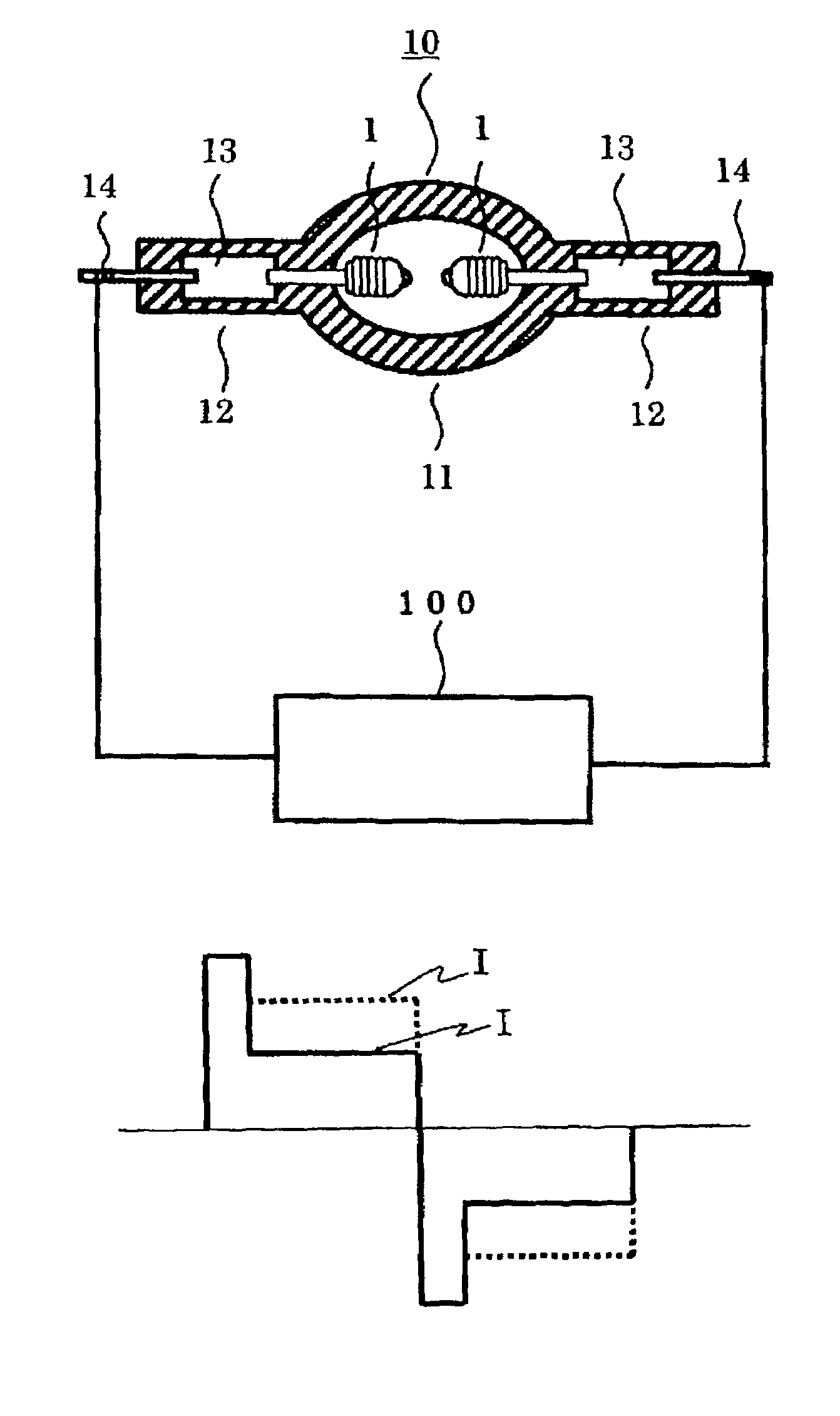
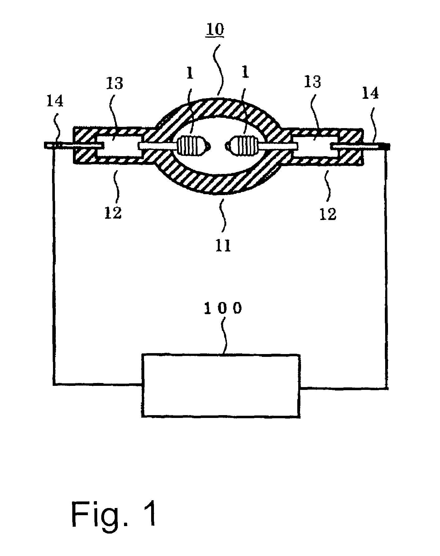
[0034]FIG. 1 schematically shows essentially the entire arrangement of the emission device of the invention for an ultra-high pressure mercury lamp. The emission device has a short arc ultra-high pressure mercury lamp 10 (hereinafter also called only a “discharge lamp”) and an operating device 100.

[0035]In the figure, the discharge lamp 10 has an essentially spherical discharge vessel 11 which is formed by a silica glass. In this discharge vessel 11, there is a pair of opposed electrodes 1 which have tungsten as their main component. From the two ends of the discharge vessel 11, there extend hermetically sealed portions 12 in which, normally, a molybdenum conductive metal foil 13 is hermetically installed, for example, by a shrink seal. For each of the electrodes 1, the shaft is electrically connected to a metal foil 13 by welding. An outer lead 14, which projects to the outside, is welded to the other end of the respective metal foil 13. The outer lead 14 is connected to the operat...


PUM


Abstract

An emission device for an ultra-high pressure mercury lamp which maintains an electrode tip shape by which a stable discharge can always be carried out is achieved for a short arc ultra-high pressure mercury lamp with silica glass arc tube containing a pair of opposed electrodes spaced apart a distance of at most 2 mm and in which the arc tube is filled with at least 0.15 mg/mm3 of mercury, a rare gas and a halogen in the range from 1×10⁻⁶ μmole/mm3 to 1×10⁻² μmole/mm3; by providing an operating device which produces a current feed by which the surface of the tip of at least one of the electrodes is shifted into a molten state during lamp operation.

Description

BACKGROUND OF THE INVENTION[0001]1. Field of the Invention[0002]The invention relates to an emission device for an ultra-high pressure mercury lamp. The invention relates especially to an emission device which is used for a liquid crystal display device with a light source which is a short arc ultra-high pressure mercury lamp in which an arc tube is filled with at least 0.15 mg / mm3 of mercury, and in which the mercury vapor pressure during operation is at least 110 atm, and for a projector device such as a DLP (digital light processor) or the like using a DMD (digital micro mirror device).[0003]2. Description of the Prior Art[0004]In a display device of the projection type, there is a demand for illumination onto an image device in a uniform manner, and moreover, with adequate color rendering. Therefore, the light source is a metal halide lamp which is filled with mercury and a metal halide. Furthermore, recently smaller and smaller metal halide lamps and more and more often point l...

Claims


Application Information

Patent Timeline
Patent Type & Authority Patents(United States)
IPC IPC(8): H01J17/20H05B41/24H01J61/073H01J61/16H01J61/20H01J61/82H01J61/86H01J61/88H05B41/282H05B41/292
CPCH01J61/0732H01J61/822H01J61/86H05B41/2928Y02B20/208Y02B20/00
Inventor TUKAMOTO, TAKUYASUZUKI, YOSHIKAZUARIMOTO, TOMOYOSHI
Owner USHIO DENKI KK
Why Eureka
Try Eureka