Orifice body with mixing chamber for abrasive water jet cutting

Inactive Publication Date: 2005-08-23
SILICON VALLEY BANK
View PDF21 Cites 34 Cited by
  • Summary
  • Abstract
  • Description
  • Claims
  • Application Information

AI Technical Summary

Benefits of technology

[0006]The present invention concerns improvements to the design and operation of nozzle assemblies for use with ultra-high pressure fluid jet cutting apparatus. In particular, the improvements concern the orifice assembly, also known in the art as the jewel holder. It is an object of the invention to provide an orifice assembly having an improved inlet chamber geometry at the interface between an inlet body and the orifice that defines the diameter of jetting water so as to optimize the column of high pressure water emanating from the orifice. It also is an object of the invention to provide for a soft seal at the interface between an inlet body and the orifice assembly so that a user may remove and install the orifice assembly by hand. It is a further object of the invention to provide for a tapered interface between the orifice assembly and a nozzle so that the axial alignment between the jewel orifice and the nozzle bore remains in close tolerance.
[0007]The orifice assembly of the present invention compri

Problems solved by technology

While many components of the overall system are subject to wear, both the precisely formed orifice and components downstream therefrom are particularly subject to wear due to the presence of abrasive material

Method used


Image

  • Orifice body with mixing chamber for abrasive water jet cutting
  • Orifice body with mixing chamber for abrasive water jet cutting
  • Orifice body with mixing chamber for abrasive water jet cutting

Examples


Embodiment Construction

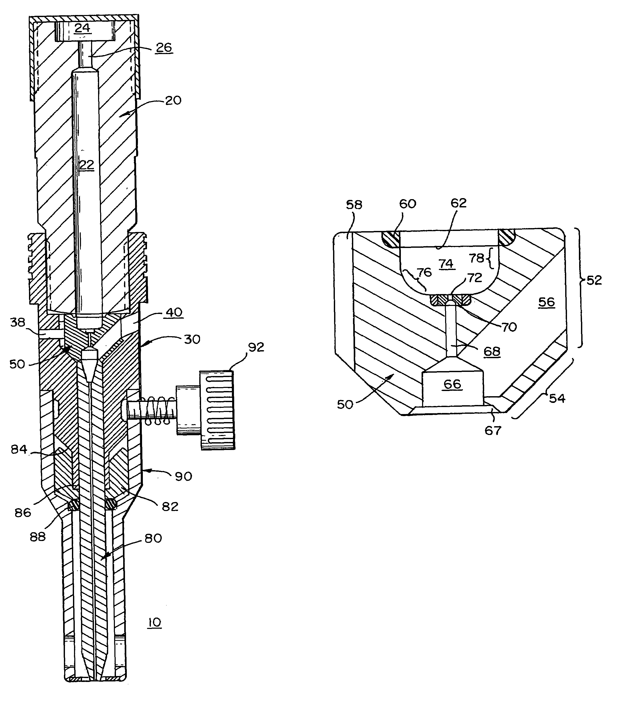
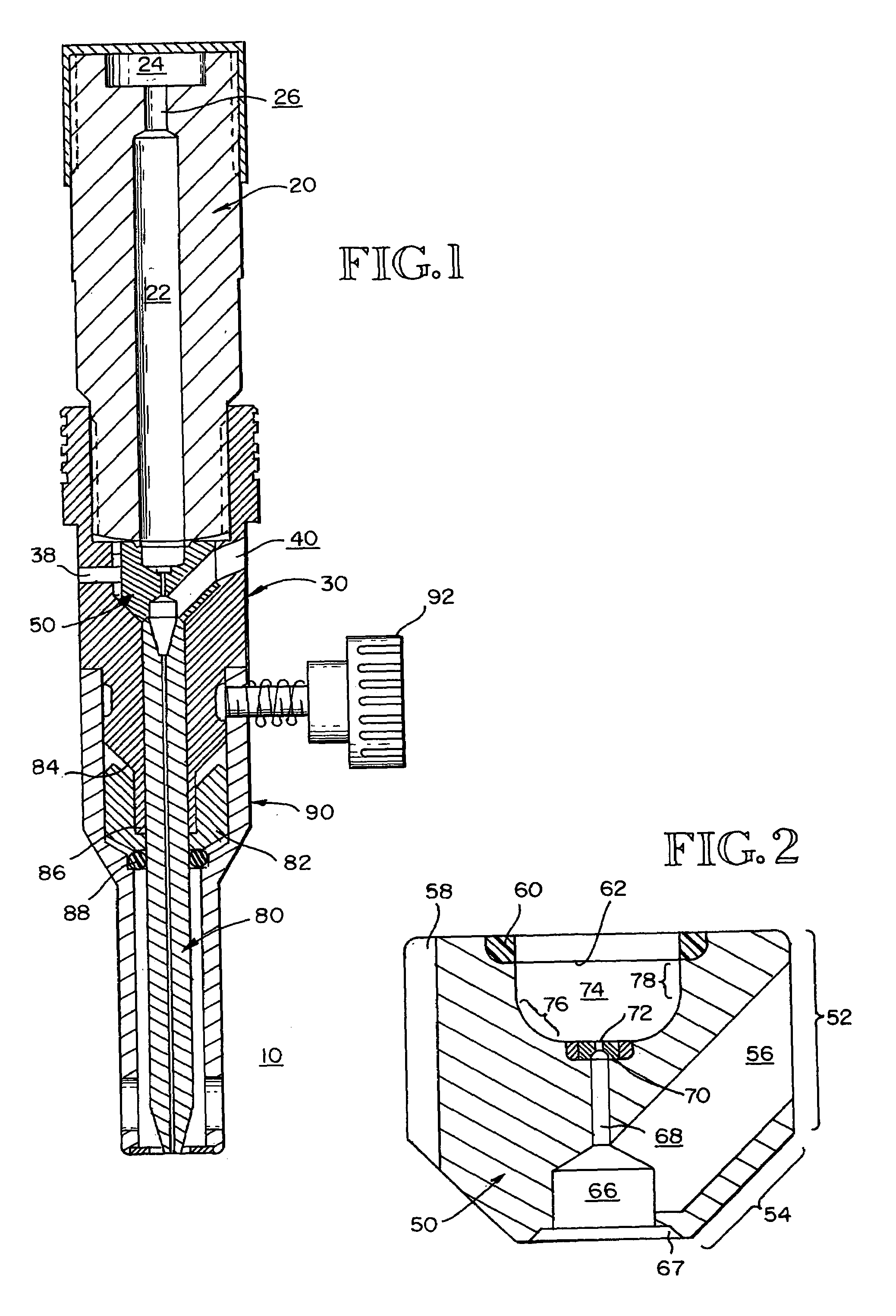
[0016]Turning now to the several figures wherein like numbers indicate like parts, and more particularly to FIG. 1, nozzle assembly 10 is shown in cross-section. Nozzle assembly 10 has five major components, namely inlet body 20, nozzle body 30, orifice assembly or jewel holder 50, mixing tube 80, and nozzle guard 90. More detailed views of each of these complements can be found in the several sheets of drawings. Unless otherwise noted, all components except for the mixing tube are formed from high tensile strength steel so as to withstand hydrostatic pressures and related hydrodynamic shock loads during operation of nozzle assembly 10.

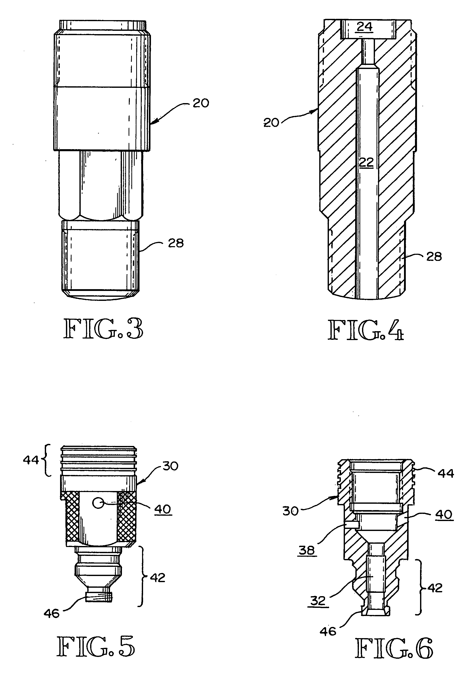
[0017]Turning first to inlet body 20, a detailed view can be found in FIGS. 3 and 4. As shown therein, inlet body 20 defines central bore 22, recessed seat 24, and reduced diameter portion 26, which are all coaxial with each other. Present on the outer portion of inlet body 20 is threaded portion 28 to engage complimentary threads on threaded portion ...


PUM

PropertyMeasurementUnit
Angleaaaaaaaaaa
Pressureaaaaaaaaaa
Flow rateaaaaaaaaaa

Abstract

An improved orifice assembly for use with an ultra high pressure fluid jet cutting apparatus is disclosed. The improved orifice assembly generally includes an orifice body defining a central bore, a high pressure inlet cavity located at an upstream portion of the body, a mixing cavity located at a downstream portion of the body, and an abrasive material inlet bore that is in direct communication with the mixing cavity. The inlet or high pressure cavity preferably has a cylindrical cross section at the side wall portion and a generally flat bottom wall, with a constant radius transition portion between the side and bottom walls. A jeweled orifice is preferably located at the bottom wall and forms a portion thereof. A chamfer at the downstream portion of the mixing chamber permits appropriate coaxial alignment of a mixing tube with the jeweled orifice so as to preserve proper fluid flow characteristics. In addition, the incorporation of a soft seal between the mating surfaces of the inlet body and the orifice assembly permit easy user removal of these components from a cutting jet system.

Description

TECHNICAL FIELD[0001]The present invention relates to the field of ultra-high pressure fluid jet cutting apparatus and more particularly to improvements concerning nozzles therefor.BACKGROUND OF THE INVENTION[0002]The field of ultra-high pressure fluid jet cutting technology has seen many advances from its infancy in the early to mid 1970's until the present. Fluid pump technology has advanced to the point that pressures in excess of 60,000 psi are routinely used in commercial settings; material science advances have increased the longevity of the wear components. This, of course, is not to say that all that can be invented has been invented.[0003]The basic components of an ultra-high pressure fluid jet cutting system include a pump for providing a source of ultra-high pressure fluid and a nozzle assembly. The nozzle assembly generally comprises an inlet body, a precisely formed orifice for creating a jet of ultra-high pressure fluid, a mixing chamber for receiving and integrating a...

Claims


Application Information

Patent Timeline
IPC IPC(8): B05B1/00B05B7/04B24C1/04B24C5/04B24C7/00
CPCB05B7/04B24C1/045B24C5/04B24C7/0007
Inventor ZENG, JIYUE
Owner SILICON VALLEY BANK
Why Eureka
Try Eureka