Image display system

a technology of image display and display frame, applied in the field of image display system, can solve the problems of inability to display real-time moving image, increase network traffic, and worse response, so as to reduce the number of moving image frames, improve response, and inhibit network traffic

Inactive Publication Date: 2005-10-20
SEIKO EPSON CORP
View PDF5 Cites 24 Cited by
  • Summary
  • Abstract
  • Description
  • Claims
  • Application Information

AI Technical Summary

Benefits of technology

[0058] As described above, as shown in FIG. 1, with an image display system 10 of this embodiment, it is possible to display an image on a display screen 60 of a PC 100, and also to display an image on a projections display screen 70 by way of a projector 200 connected via a network 300. It is also possible to obtain the effects described below with the image display system 10 of this embodiment.
[0059]FIG. 5 is an explanatory diagram showing the effect of the image display system of this embodiment. With the image display system 10 of this embodiment, as shown in FIG. 5(A), when a moving image MVn is displayed on a display screen 60 of a PC 100, image data MV-D of each frame of this moving image MVn is sent via a network 300, and this moving image MVn is displayed on a projection display screen 70 by way of a projector 200. Then, as shown in FIG. 5(B), when the moving image MVn is expanded and an expanded moving image Mvs is displayed on the display screen 60 of the PC 100, it is possible to display the expanded moving image Mvs by way of the projector 200 on the projection display screen 70 as

Problems solved by technology

Because of this, when the size of the change area is large and the data volume of the image data to be transferred is large, there is the problem that the network traffic increases, and the response worsens.
As a result, when displaying a moving image at the expanded screen size

Method used


Image

  • Image display system
  • Image display system
  • Image display system

Examples


example 5

D5. Variation Example 5

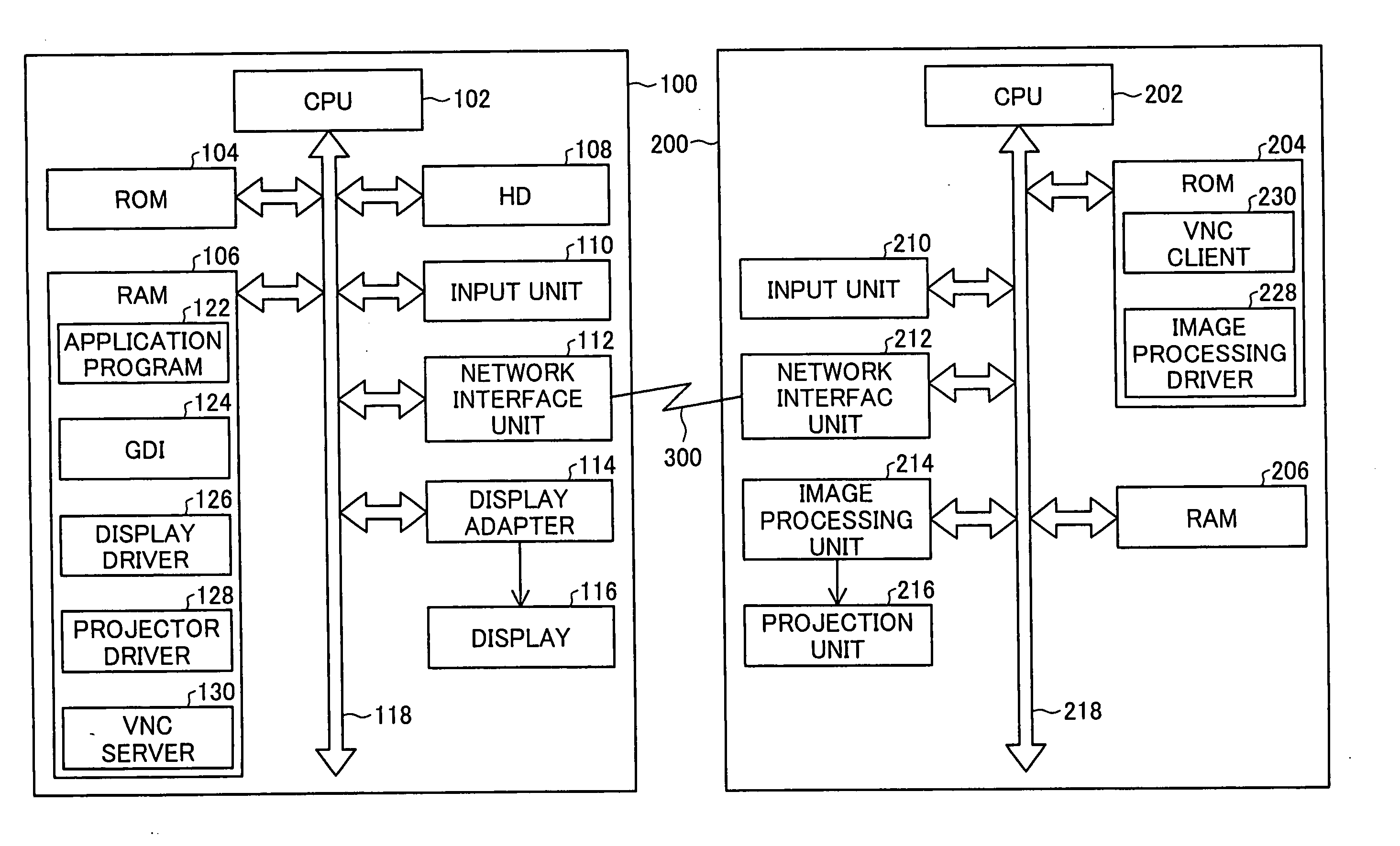
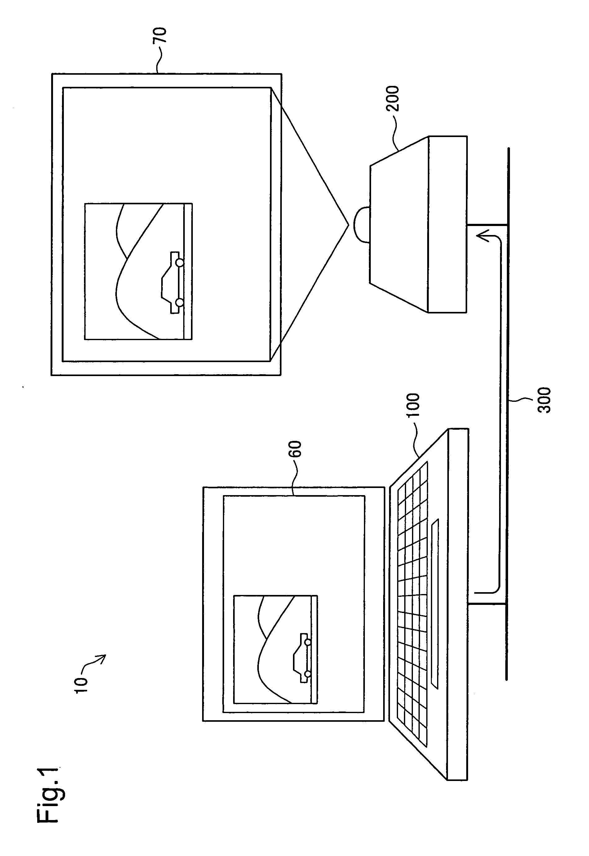
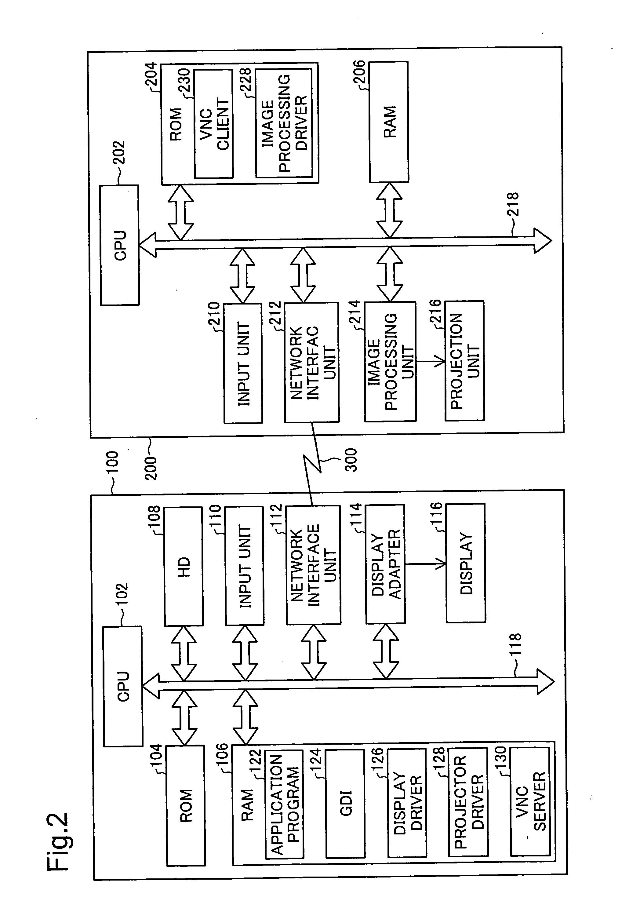
[0066] Also, the embodiments noted above, a notebook PC was used as the image supply device, but it is also possible to use a desktop PC. Instead of a PC, it is also possible to use a server computer, a mobile computer, a hand held computer, a workstation or the like. Instead of these computers, it is also possible to use a device that can be connected to a network and has the same functions as a computer. Included in that kind of device would be, for example, a portable data terminal, a mobile telephone, a mail terminal, a game device, a set top box or the like.

D6. Variation Example 6

[0067] Also, as a network, in addition to a local area network (LAN), it is also possible to use various networks such as a wide area network (WAN), the internet, intranet or the like. The network may also be constructed as a wired network, or may be constructed as a wireless network.


PUM


Abstract

An image display system comprising an image supply device, a projector, and a network for connecting the image supply device and the projector, and when images are supplied to the projector via the network from the image supply device, the images are projected by the projector. When projecting and displaying a second image having a second image size based on a first image having a first image size in a projection screen of the projector, the image supply device generates supplied image data including first image data for representing the first image, position data for indicating the display position of the second image in the projection screen, and second image size data for indicating the second image size, and also supplies this to the projector via the network. By doing this, an increase in network traffic is suppressed for the image display system noted above.

Description

BACKGROUND OF THE INVENTION [0001] 1. Field of the Invention [0002] The present invention relates to an image display system comprising an image supply device and a projector connected via a network, and particularly relates to an image display system that is suitable for displaying of moving images. [0003] 2. Description of the Related Art [0004] In the past, a projector for which a personal computer (hereafter abbreviated as “PC”) which is an image supply device and a projector are connected via a network, and that is able to supply and display an image from the PC to the projector (hereafter called a “network projector”) was proposed (e.g. see International Publication Pamphlet No. 01 / 093583). [0005] Also, an art called VNC (Virtual Network Computing) is used to supply images from a PC via a network to this kind of network projector. [0006] However, with VNC, of the images generated by the image supply device, image data of the area for which the image has changed (change area) (...

Claims


Application Information

Patent Timeline
IPC IPC(8): G06F3/14G06F13/00G06F3/153G09G5/00G09G5/36H04L12/00H04L29/08H04N1/00H04N5/14H04N5/74H04N5/775H04N5/781
CPCG06F3/1415G06F3/1462G06F3/147G09G2340/0407G09G2340/0414G09G2340/0421G09G2340/0471G09G2340/0478G09G2340/14G09G2370/04H04N5/14H04N5/74H04N5/775H04N5/781H04L67/12
Inventor KARASAWA, TORU
Owner SEIKO EPSON CORP
Why Eureka
Try Eureka