Body condition measuring device
- Summary
- Abstract
- Description
- Claims
- Application Information
AI Technical Summary
Benefits of technology
Problems solved by technology
Method used
Image

Examples
first embodiment
[0049] In the following description, a pulse wave sensor that is attached around a wrist of a human body and detects pulse waves will be taken as an example of a body condition measuring device.
[0050] (a) First, description will be given to the configuration of the pulse wave sensor in this embodiment with reference to FIG. 1.
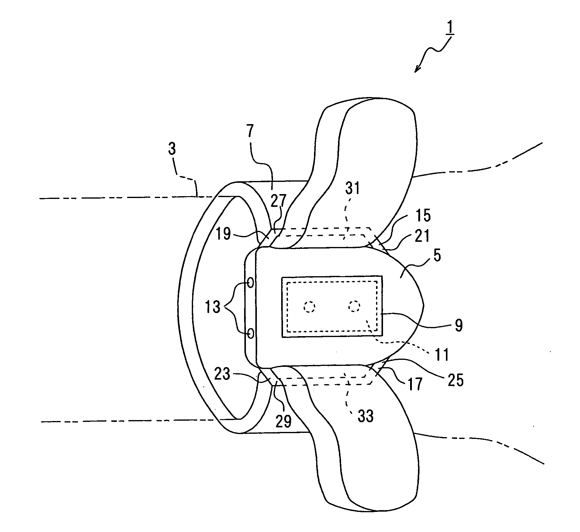
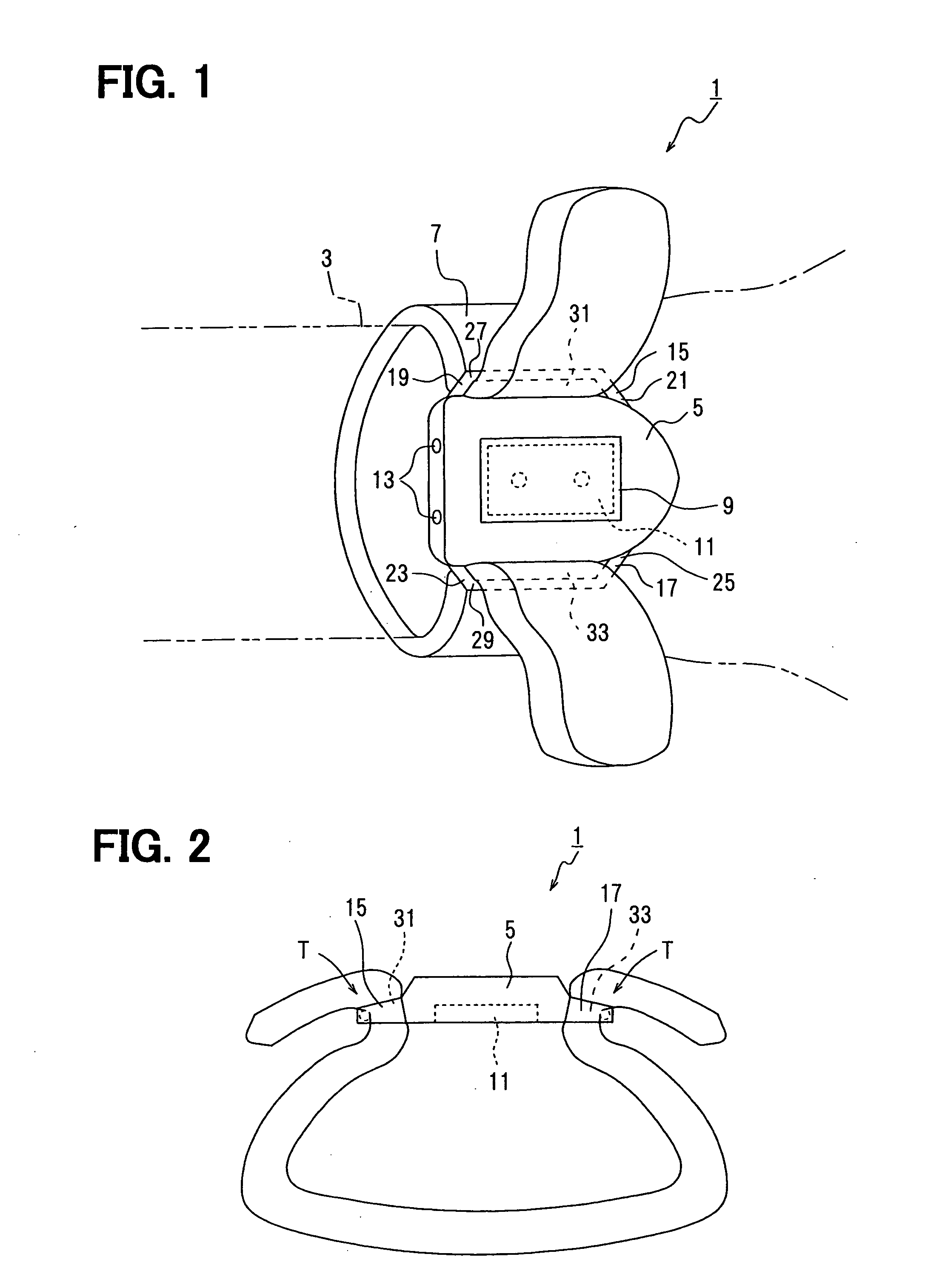
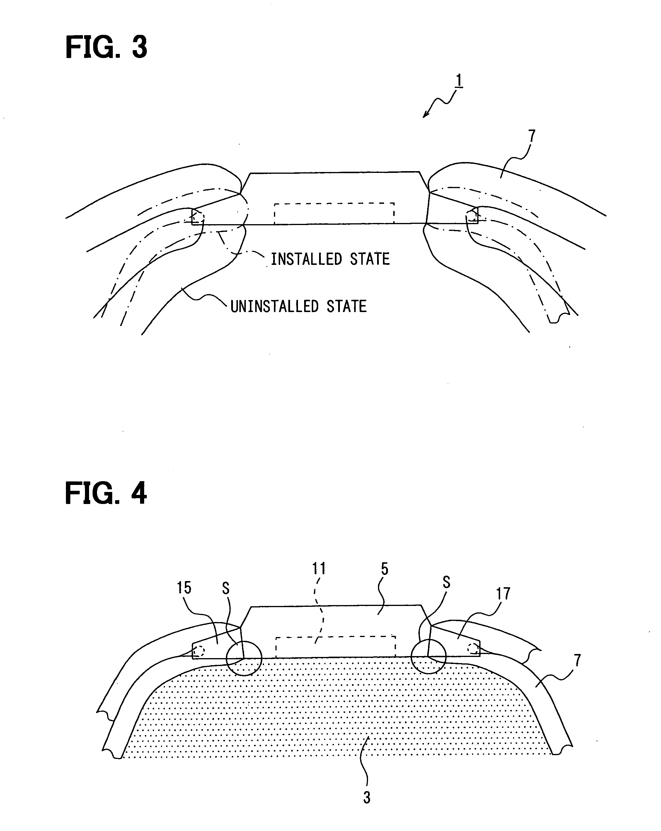
[0051] As illustrated in FIG. 1, the pulse wave sensor 1 in this embodiment is a wrist watch-type sensor so designed that it is attached around, for example, a wrist 3 of a human body. The pulse wave sensor 1 includes a pulse wave sensor main unit 5 and a band 7. The band 7 attaches the pulse wave sensor main unit 5 around the wrist 3.
[0052] The pulse wave sensor main unit 5 is a plate-like member, which is shaped into generally a boat form having a tapered end. The pulse wave sensor main body 5 protrudes in the direction of the end of the hand (to the right in FIG. 1). That is, the sensor main unit 5 is asymmetric in the left-right direction of FIG. 1 (the ...
second embodiment
[0080] Description will be given to a pulse wave sensor in a second embodiment. The same description as of the first embodiment will be omitted.
[0081] As illustrated in FIG. 6A, the pulse wave sensor 51 in this embodiment comprises a plate-like pulse wave sensor main unit 52 and an elastic long strip-shaped band 55, like that in the first embodiment.
[0082] In this embodiment, especially, the band 55 is provided at its both ends with substantially triangular prismatic projections 57 and 59.
[0083] As illustrated in FIG. 6B, these projections 57 and 59 are larger in outer dimensions than the main part 63 of the long strip-shaped band. (FIG. 6B is a schematic diagram wherein the portion marked with “VIB” in FIG. 6A is disposed over the band anchoring portion 61 for the purpose of comparison of size.) Thus, the dimensions of the projections 57 and 59 are considerably larger than the inner dimensions of the band insertion holes 65 in the band anchoring portions 61, and the projections ...
third embodiment
[0086] Description will be given to a pulse wave sensor in a third embodiment. The same description as of the first embodiment will be omitted.
[0087] As illustrated in FIG. 7, the pulse wave sensor 71 in this embodiment comprises a plate-like pulse wave sensor main unit 73 and an elastic long strip-shaped band 75, like that in the first embodiment.
[0088] In this embodiment, especially, one end (the left end in the figure) of the band 75 is fixed in proximity to one band anchoring portion 77. More specific description will be given. One end (fixed end) of the band 75 is passed through the band insertion hole 79 and looped around a pin 81. In this state, the one end is secured on the outer surface of the band main part 83 by sewing, bonding, or the like.
[0089] The other end (the right end in the figure) of the band 75 is passed through the band insertion hole 87 in the other band anchoring portion 85. The degree to which the band 75 is tightened can be adjusted by pulling the other...
PUM
 Abstract
Description
Claims
Application Information
PatSnap Eureka turns technology decisions into work you can execute. Powered by our Innovation Knowledge Graph, it runs expert workflows across engineering, life sciences, materials and intellectual property. Get your review-ready output in minutes.


