Predictive modeling of machining line variation

a technology of machining line variation and prediction modeling, applied in the field of multi-stage manufacturing system, can solve the problems of inability to predict the variation of machining line, inability to fully control the total factory, and long technique time,

Active Publication Date: 2005-10-20
GM GLOBAL TECH OPERATIONS LLC
View PDF7 Cites 25 Cited by
  • Summary
  • Abstract
  • Description
  • Claims
  • Application Information

AI Technical Summary

Problems solved by technology

However, MMS are also widely employed in complex fabrication systems, e.g. semi-conductor fabrication, and complex machining systems, e.g. internal combustion engine block and head machining.
However, such techniques tend to be lengthy and not generally well structured and understood with respect to specific manufacturing variables.
Complex machining processes, however, include a variety of inputs and sensitivities not generally shared by assembly systems or other types of manufacturing systems.

Method used


Image

  • Predictive modeling of machining line variation
  • Predictive modeling of machining line variation
  • Predictive modeling of machining line variation

Examples


Embodiment Construction

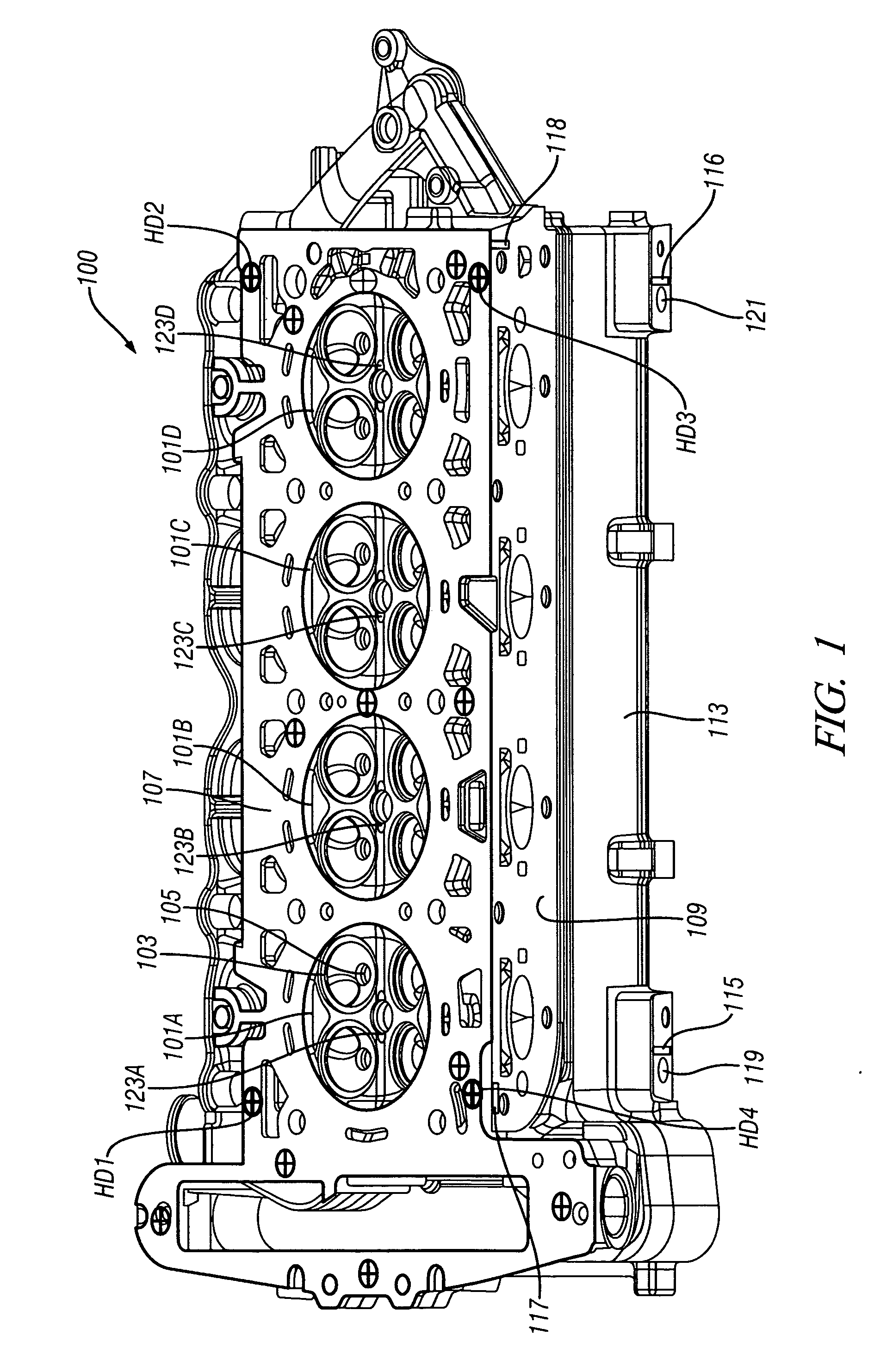
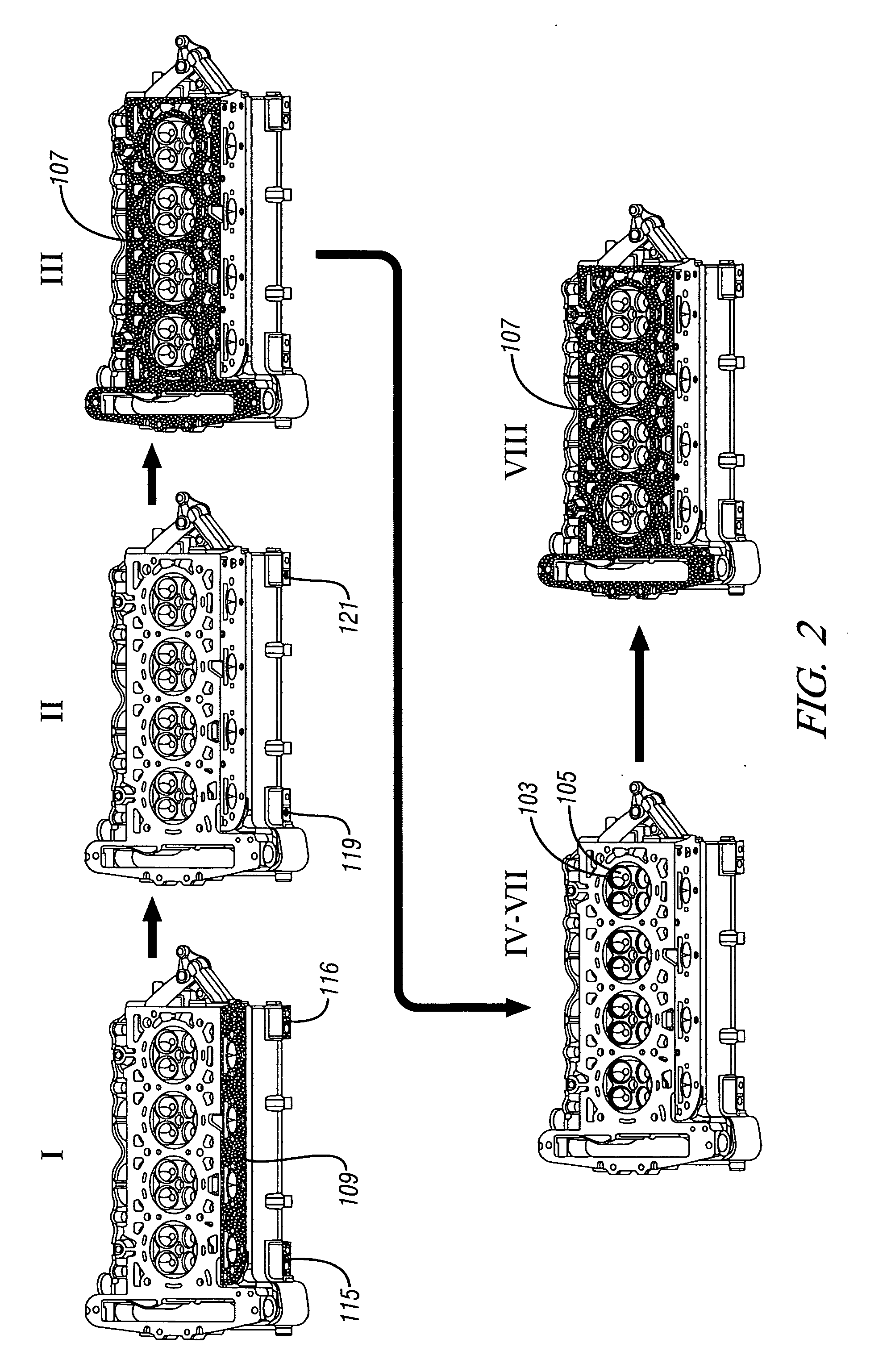
[0026] The present invention will now be described with respect to an exemplary multistage manufacturing system comprising a plurality of operations and stations within the operations for the production of an internal combustion engine cylinder head assembly. The manufacturing process is defined at a front end by a material or workpiece input—in the present example a cylinder head casting—and at the back end by a final product—in the present example a completely machined cylinder head. In practice with respect to exemplifying the present invention, the manufacturing process is further delimited with respect to particular operations and stations having been identified as potentially significantly influencing a predetermined feature of interest. Features as used herein and as understood by one having ordinary skill in the art are understood to include geometric aspects of the machined work piece. In the present example, the feature of interest is the deck face of the cylinder head as ...


PUM


Abstract

A multistage machining process includes a plurality of stations. Workpiece feature quality is predicted based on decomposition of the machining process into sources of variation, reticulation of the machining process into machining stations and error models that account for significant contributions to feature quality including from categorical sources of variation.

Description

CROSS REFERENCE TO RELATED APPLICATIONS [0001] This application claims priority to U.S. provisional patent application Ser. No. 60 / 562,144 filed on Apr. 14, 2004, which is hereby incorporated herein by reference in its entirety.TECHNICAL FIELD [0002] The present invention is related to production systems. More particularly, the invention concerns multistage manufacturing systems. BACKGROUND OF THE INVENTION [0003] Multistage manufacturing systems (MMS) are commonplace, diverse in variety and are employed in various aspects of many manufacturing industries. Complex mechanical assemblies, such as automatic transmissions, and vehicle assembly plant processes, such as body assembly operations, are examples of MMS related specifically to assembly systems. However, MMS are also widely employed in complex fabrication systems, e.g. semi-conductor fabrication, and complex machining systems, e.g. internal combustion engine block and head machining. Some hybrid MMS include aspects from multipl...

Claims


Application Information

Patent Timeline
Patent Type & Authority Applications(United States)
IPC IPC(8): G05B19/418G06F19/00
CPCG05B19/41875G05B2219/32223G05B2219/32194Y02P90/02
Inventor AGAPIOU, JOHN S.STEINHILPER, ERIC A.ALDEN, JEFFREY M.ANAGONYE, ALOYSIUSBANDYOPADHYAY, PULAKGU, FANGMINGHILBER, PATRICK M.
Owner GM GLOBAL TECH OPERATIONS LLC
Why Eureka
Try Eureka