
Method to manage memory in a platform with virtual machines

a virtual machine and memory technology, applied in the field of managing memory, can solve the problems of inability to dynamically create and delete vm sessions efficiently, 34 of the available memory is idle and unused, and memory is not available for swapping

Active Publication Date: 2005-10-20
TAHOE RES LTD
View PDF12 Cites 138 Cited by
  • Summary
  • Abstract
  • Description
  • Claims
  • Application Information

AI Technical Summary

Benefits of technology

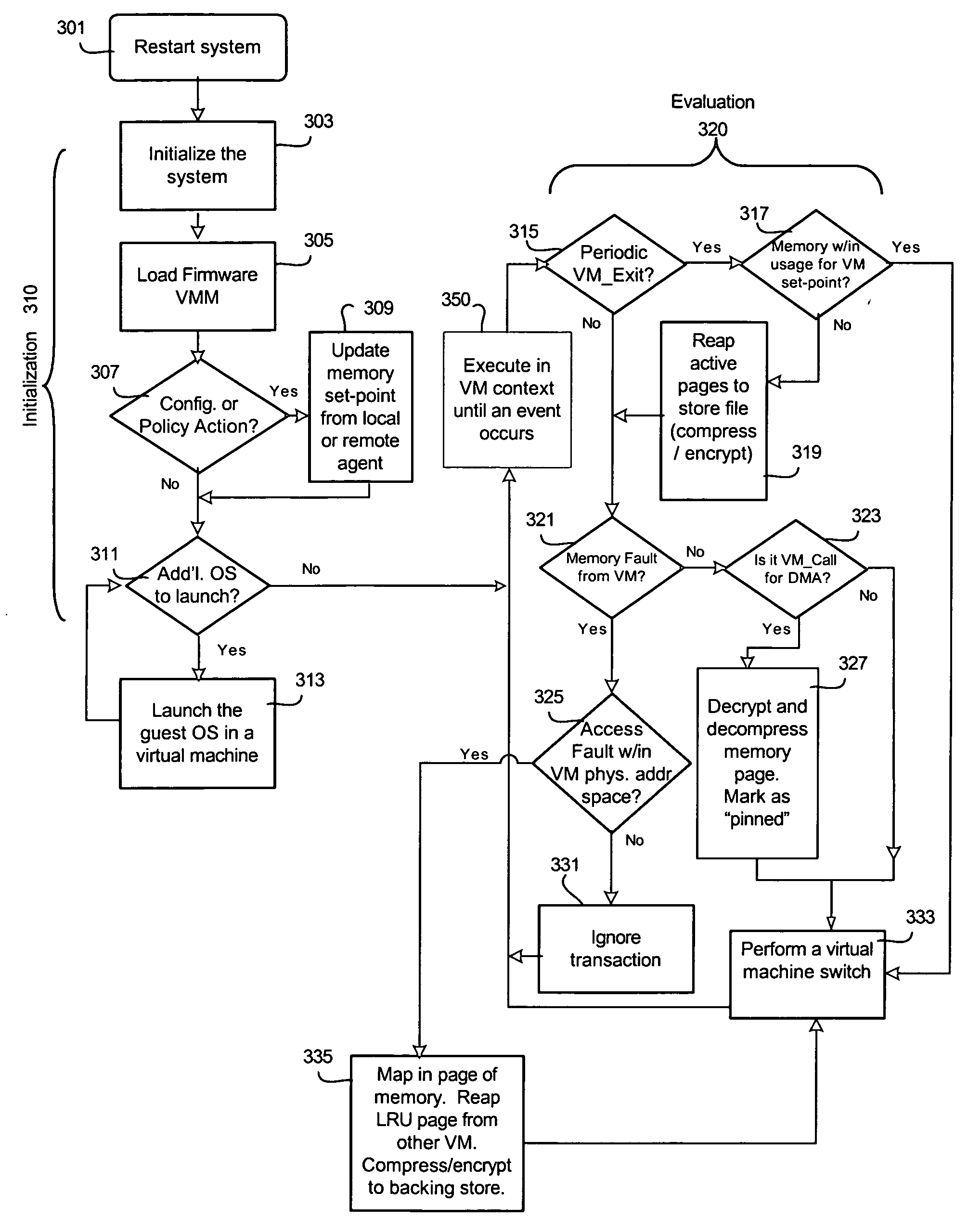
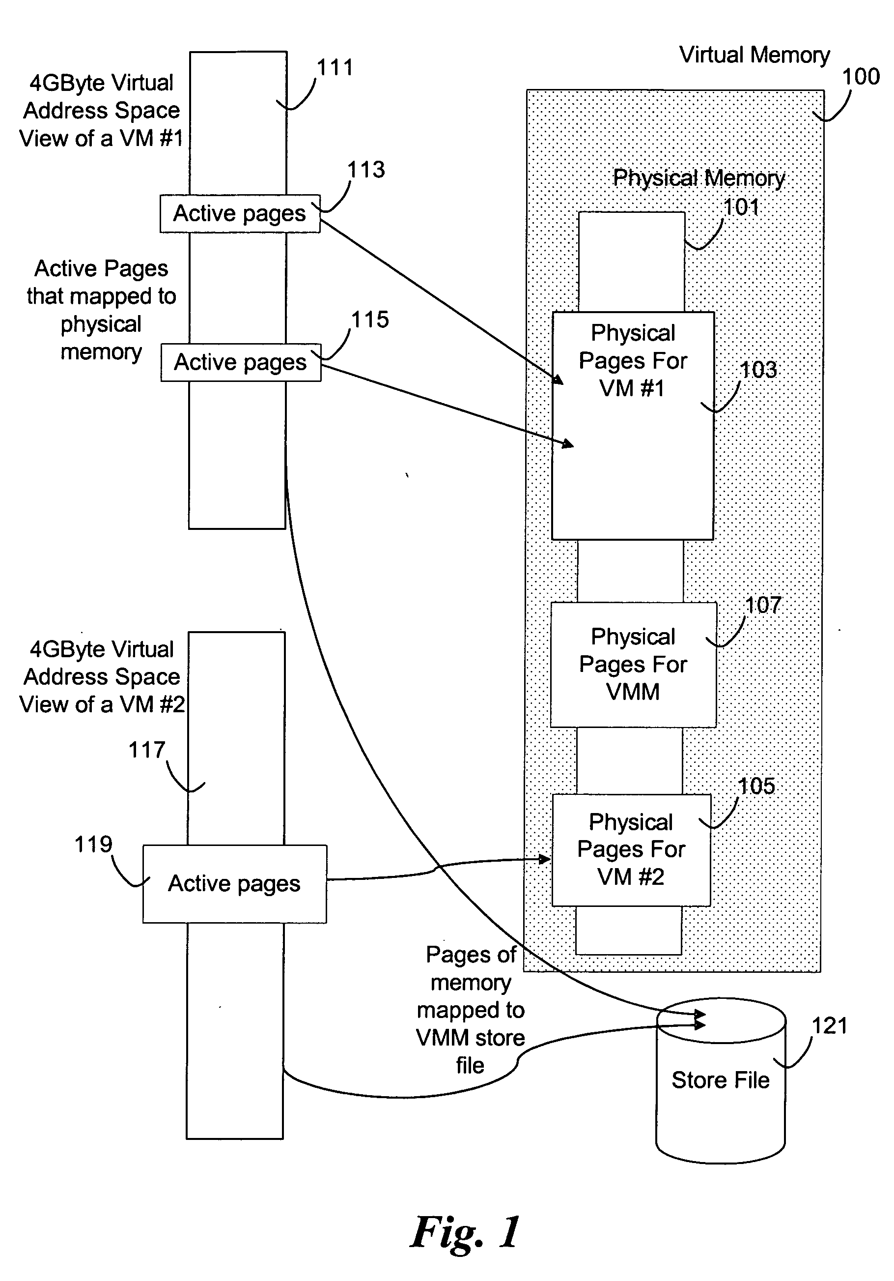
[0015] The VMM defines a level of abstraction of a memory partition. In other words, if two partitions of physical memory are generated from the allocated physical memory, the VMM makes it appear to each of two guest OSs that their memory allocation begins at address zero. In reality, the guest OSs will be assigned a portion of physical memory according to the defined partitions. In existing systems, the VMM uses one-stage mapping, i.e., maps the virtual address known by the guest OS to physical memory, with no swapping. In one example, there is 256 MB of physical memory partitioned to two guest VMs, each OS in a guest VM has a prescribed, or virtual, 0-128 MB address space. In one example, Windows® runs in one VM and Linux runs in a second VM. The Linux OS may actually be assigned physical memory in address range 128-256 MB, but it appears to Linux that the Linux OS is using memory in the virtual address range 0-128 MB. The VMM maps the virtual memory address to the physical memory address. In this scenario, the VMM applies a fixed offset translation from virtual address range 0-128 MB to physical address range 0-128 MB or 128-256 MB. An embodiment of the present invention enables the VMM to more fully manage virtual memory among guest VMs, including reallocation of partitions.

Problems solved by technology

A problem with this method is the inability to dynamically create and delete VM sessions efficiently, regarding the use of available physical memory resources.
Thus, when only two sessions are running, ¾ of the available memory is idle and unused.
In normal operation of existing systems, some memory is not available for swapping.
In a virtual environment of an existing system, virtualization of VM memory is not possible by a virtual machine monitor because some pages are non-swappable.
The VMMs of existing systems will not be able to accommodate memory that is not available for swapping, with respect to the guest VM OS.

Method used


Image

  • Method to manage memory in a platform with virtual machines
  • Method to manage memory in a platform with virtual machines
  • Method to manage memory in a platform with virtual machines

Examples


Embodiment Construction

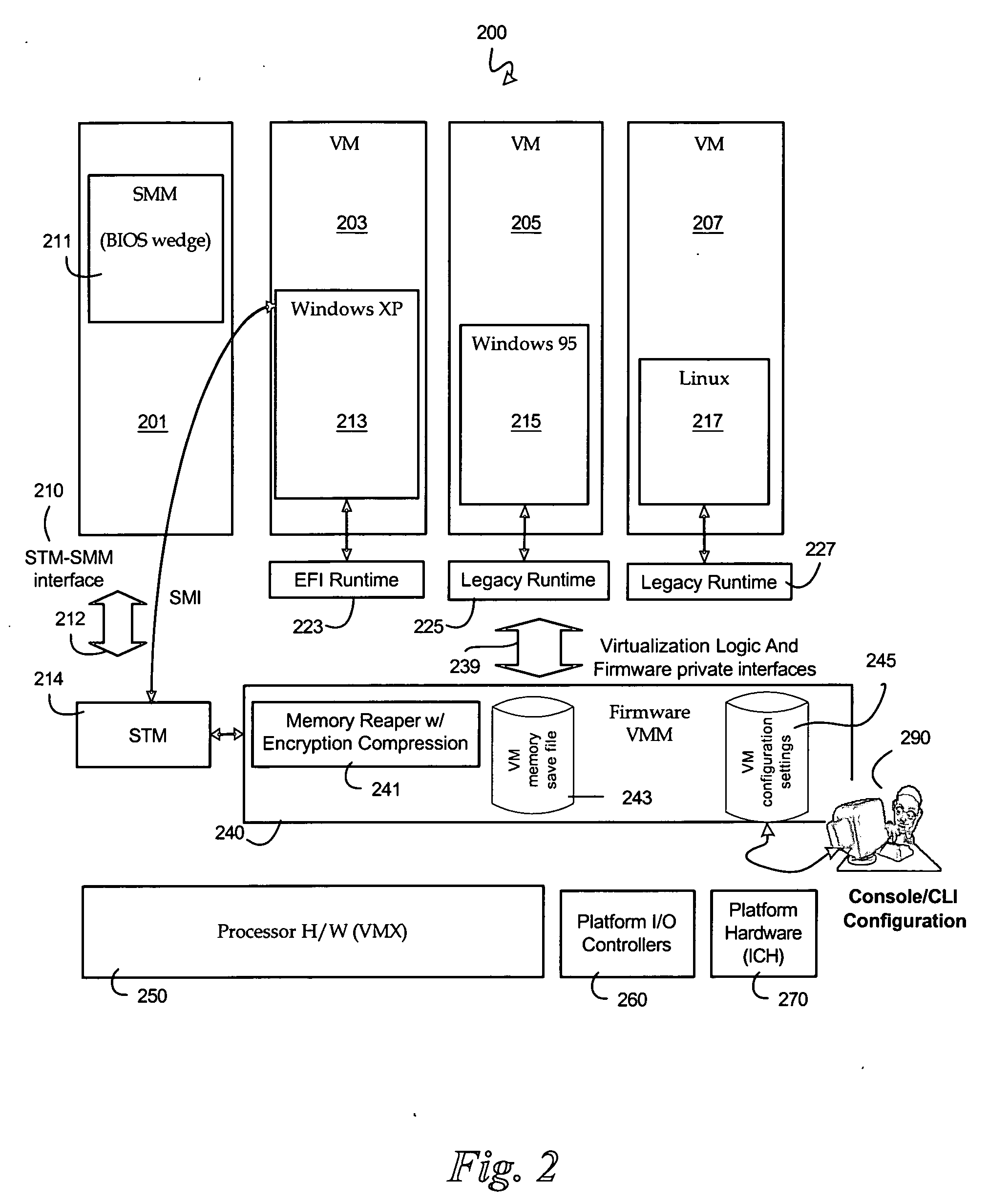
[0009] An embodiment of the present invention is a system and method relating to managing memory in a virtualization platform by a virtual machine monitor (VMM). In at least one embodiment, the present invention is intended to allow dynamic allocation of memory to one or more virtual machines running on a virtual machine platform.

[0010] Reference in the specification to “one embodiment” or “an embodiment” of the present invention means that a particular feature, structure or characteristic described in connection with the embodiment is included in at least one embodiment of the present invention. Thus, the appearances of the phrase “in one embodiment” appearing in various places throughout the specification are not necessarily all referring to the same embodiment.

[0011] In existing systems, the VMM does not know what the guest OS is doing with the memory allocated to the guest OS. Thus, the VMM cannot guarantee that non-swappable pages are not swapped out, in virtual memory scheme...


PUM


Abstract

An embodiment of the present invention enables the virtualizing of virtual memory in a virtual machine environment within a virtual machine monitor (VMM). Memory required for direct memory access (DMA) for device drivers, for example, is pinned by the VMM and prevented from being swapped out. The VMM may dynamically allocated memory resources to various virtual machines running in the platform. Other embodiments may be described and claimed.

Description

FIELD OF THE INVENTION [0001] An embodiment of the present invention relates generally to managing memory and, more specifically, to virtualizing virtual memory in a virtual machine environment within a virtual machine monitor. BACKGROUND INFORMATION [0002] Various mechanisms exist for managing memory in a virtual machine environment. A virtual machine platform typically executes an underlying layer of software called a virtual machine monitor (VMM) which hosts one to many operating system (OS) sessions, also known as virtual machines (VMs). In existing systems, a VMM controls resources on the virtualization platform, including memory. The VMM takes the amount of physical memory on the platform, i.e. 256 MB or other total, and apportions it (divides it up) among the many OSs that are hosted in the various VMs. For instance, if the virtual machine session supports Linux and Microsoft® Windows® running simultaneously, and has a total of 256 MB physical available memory, the VMM divide...

Claims


Application Information

Patent Timeline
IPC IPC(8): G06F9/455G06F9/50G06F12/00
CPCG06F9/45537G06F12/126G06F9/5016
Inventor ZIMMER, VINCENT J.ROTHMAN, MICHAEL A.
Owner TAHOE RES LTD
Learn More