Sampling device and method for measuring fluid flow and solute mass transport

a sampling device and fluid flow technology, applied in the direction of liquid/fluent solid measurement, withdrawing sample device, component separation, etc., can solve the problems of inconvenient sampling of method is clearly not suitable for sampling organic and/or inorganic solutes, and repeat sampling is costly operation, etc., to achieve accurate measurements

Active Publication Date: 2005-10-27
AARHUS UNIV
View PDF2 Cites 64 Cited by
  • Summary
  • Abstract
  • Description
  • Claims
  • Application Information

AI Technical Summary

Benefits of technology

[0042] One object of the present invention is to provide a device allowing accurate measurements of fluid flow and solute mass transport in flow systems. The device according to the invention comprises a casing having inlet and outlet openings and a fluid passageway therebetwee...

Problems solved by technology

They do not have an adsorbing material in the sampling device to gather data on the adsorption rates or chemical make-up of the surrounding media.
This method is clearly not suitable for sampling of organic and/or inorganic solutes, as the method relies on a mechanical filtering process.
Repetitive sampling is a costly operation, hence in practice, monitoring programs, for example in groundwater systems, have to compromise on the number of samples that are taken over a given period.
Several issues limit the validation and practical applicability of semi-permeable membrane devices.
This implies that the diffusion coefficient for each single monitored compound should be calibrated individually (Huckins, 1999), which complicates the quantification of the solute concentration.
Further, actual diffusion rates may be affected by bio-fouling of the membrane and/or non-ideal diffusion at higher concentrations.
After equilibrating the SPM for a certain period, the uptake of some compounds may still follow the initial linear kinetics, but other compounds will have past the linear stage, hence, quantification of the solute concentration in the fluid medium becomes less accurate, due to the non-linear response.
Fourth, SPM devices are not permeable to mobile col...

Method used


Image

  • Sampling device and method for measuring fluid flow and solute mass transport
  • Sampling device and method for measuring fluid flow and solute mass transport
  • Sampling device and method for measuring fluid flow and solute mass transport

Examples


Embodiment Construction

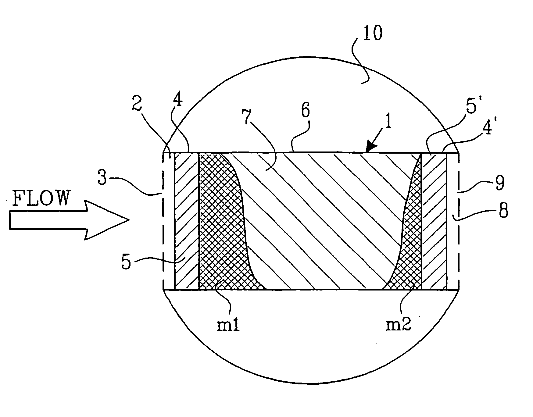
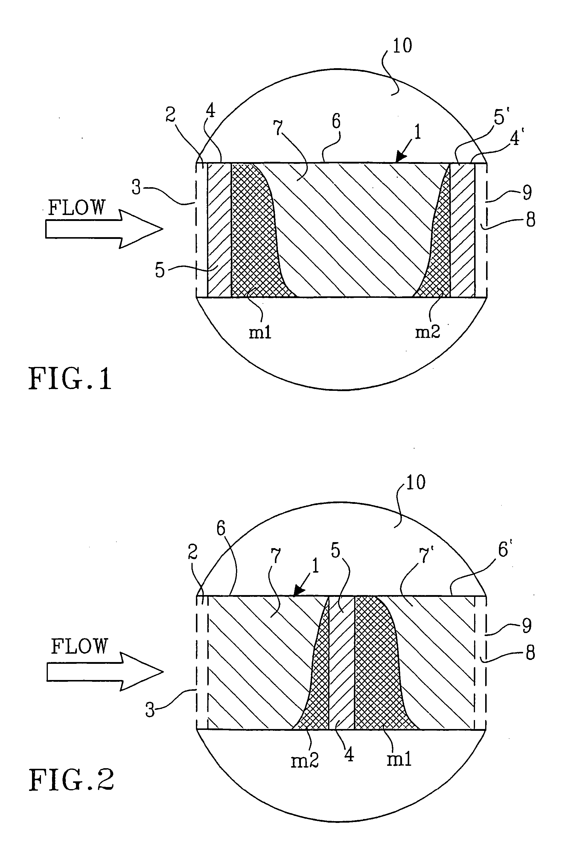
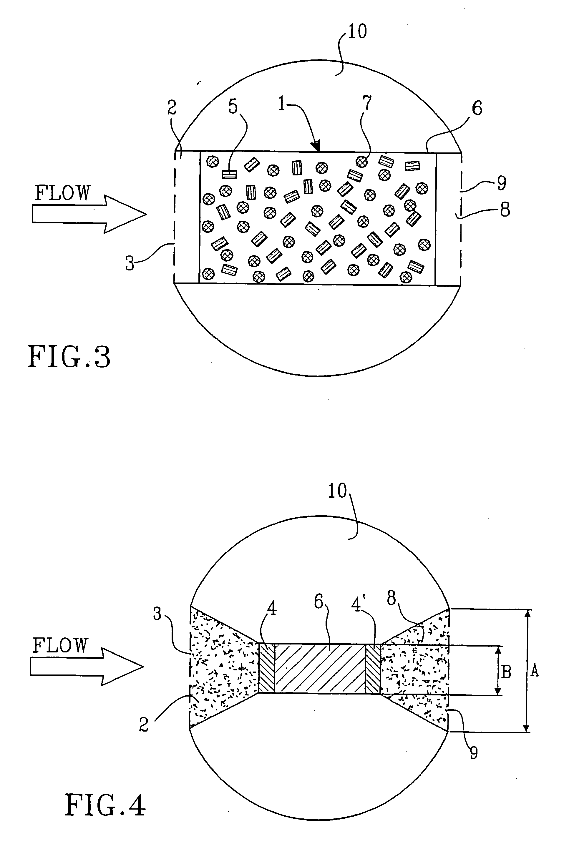
[0077] The device shown in FIG. 1 represents a simple technical configuration of the sampling device according to the invention. The device contains a casing 1 comprising an inlet section 2 having an inlet opening 3, which preferably is covered with a mesh, a perforated screen or the like, a first permeable tracer section 4 containing at least one partly soluble internal tracer 5 in a known amount and with known diffusion properties, an adsorbent matrix section 6 in the form of a permeable volume filled with an insoluble solid porous matrix 7, comprising of at least one adsorbent material that is particularly suited for the solutes of interest and the used tracers, a second permeable tracer section 4′ containing at least one partly soluble internal tracer 5′ in a known amount and with known diffusion properties, an outlet section 8 having an outlet opening 9 preferably covered with a mesh, a perforated plate or the like, and a solid housing 10 for the casing 1. The housing 10 may ei...


PUM


Abstract

A device and a method for measuring fluid flow and solute mass transport in flow systems includes a casing (1) having inlet (3) and outlet (9) openings and a fluid passageway therebetween, the casing containing at least one fluid permeable insoluble adsorbent matrix (7) and at least one tracer material (5, 5′) located in the fluid passageway. The tracer material (5,5′) is a fluid permeable partially soluble material which at least prior to installation is not physically or chemically bonded to the adsorbent matrix (7) and is either mixed with the adsorbent matrix or is located in at least one section (4,4′) of the casing (1) separate from but in contact with at least one section (6,6′) of the casing holding the insoluble adsorbent matrix (7,7′). The device is intended to be installed in a medium having a fluid path therein.

Description

TECHNICAL FIELD OF THE INVENTION [0001] The present invention relates to a device and a method for measuring fluid flow and solute mass transport in flow systems. BACKGROUND OF THE INVENTION [0002] The invention provides for the measurement of solute fluxes and viscous flow in liquid and partially saturated porous media. The solutes may be organic or inorganic molecules that are dissolved and / or attached to dispersed colloids in the liquid. More specifically, the invention relates to the monitoring of solute fluxes in water resources, including, but not limited to, variably saturated soils, sediments and groundwater aquifers, surface water, water for industrial purposes, tap water, drinking water and aqueous waste streams. [0003] Monitoring for solutes in such water resources is often needed to verify concentrations of harmful substances in relation to specific environmental standards or reference levels as proclaimed by the regulating authorities. So, the solutes that are of intere...

Claims


Application Information

Patent Timeline
IPC IPC(8): G01P5/00G01F1/704G01N1/10G01N13/00G01N33/18G01N33/24
CPCG01F1/704G01F1/7048G01N2013/003G01N33/18G01N33/24G01N13/00
Inventor DE JONGE, HUBERTROTHENBERG, GADI
Owner AARHUS UNIV
Why Eureka
Try Eureka