Reinforced structure for collapsible and wind resistible umbrella

a technology of reinforced structure and umbrella, which is applied in the field of reinforced structure for collapsible and wind-resistible umbrellas, can solve the problems of umbrellas often collapsed and ruined, weakening the mechanical strength to withstand, etc., and achieves the effects of enhancing the umbrella structure, limiting separation, and preventing the overturning of the first subsection

Inactive Publication Date: 2005-10-27
WU HSIEN SAO
View PDF6 Cites 15 Cited by
  • Summary
  • Abstract
  • Description
  • Claims
  • Application Information

AI Technical Summary

Benefits of technology

[0012] The resilient band which fixes its one end to the tailend of the first subsection of the main umbrella rib and sewes its other end onto the second umbrella cover can limit the separation between the two sub-sections of the main rib by its resiliency so as to prevent overturning of the first subsection of the main rib. The auxiliary rib bridging between the front end of the first section of the main rib and the second section of main rib can strongly enhance the umbrella structure to resist a violent wind attack.

Problems solved by technology

However, in the structure of a multi-collapsible umbrella, too many nodes for supporting umbrella ribs may results in weakening the mechanical strength to withstand the wind pressure such that the umbrella is often collapsed and ruined by a strong wind force and pouring rainfall notwithstanding the wind attacks the outer surface of the umbrella cover as a wind pressure, or attacks the inner surface thereof as an extract force.

Method used


Image

  • Reinforced structure for collapsible and wind resistible umbrella
  • Reinforced structure for collapsible and wind resistible umbrella
  • Reinforced structure for collapsible and wind resistible umbrella

Examples


Embodiment Construction

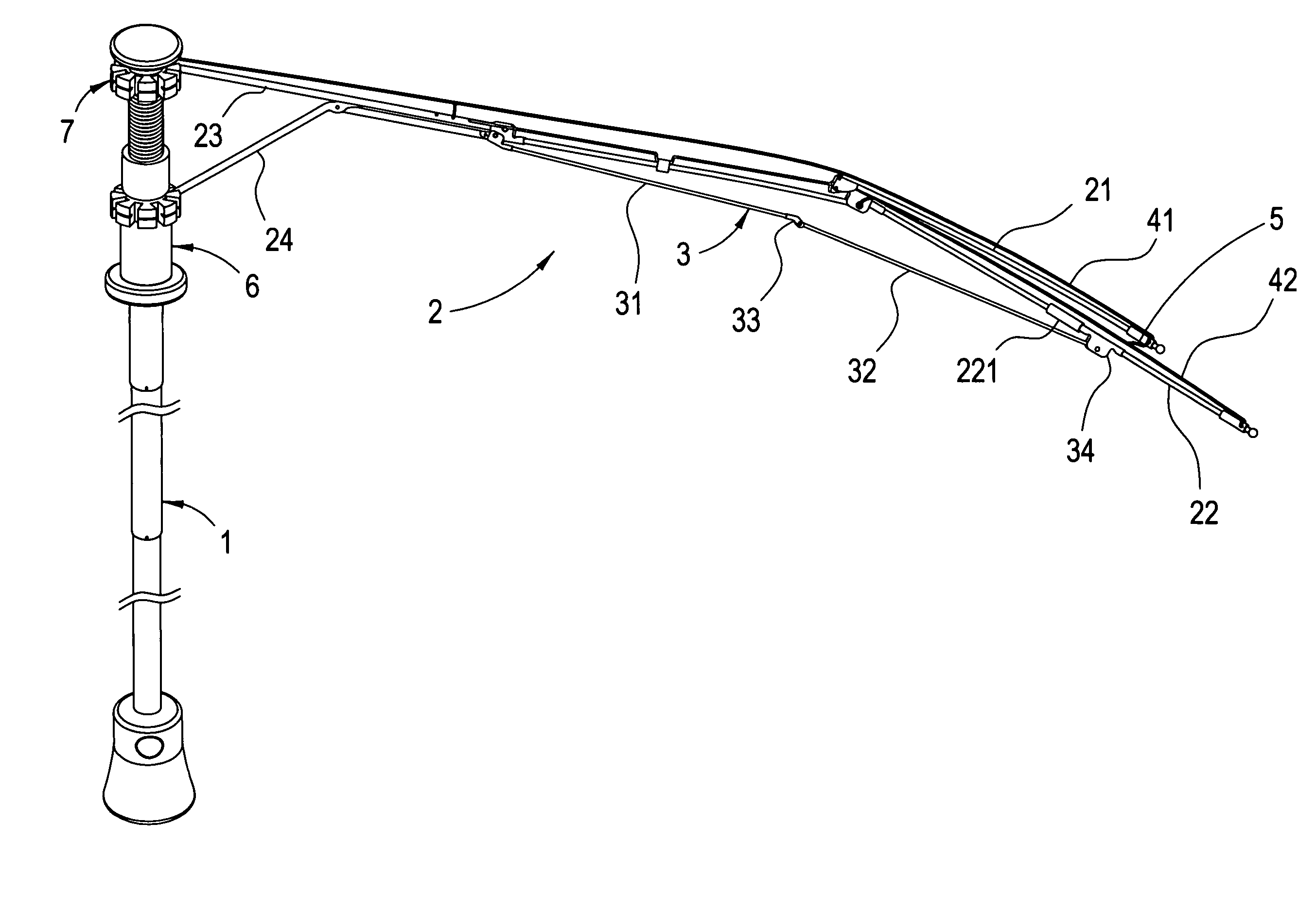
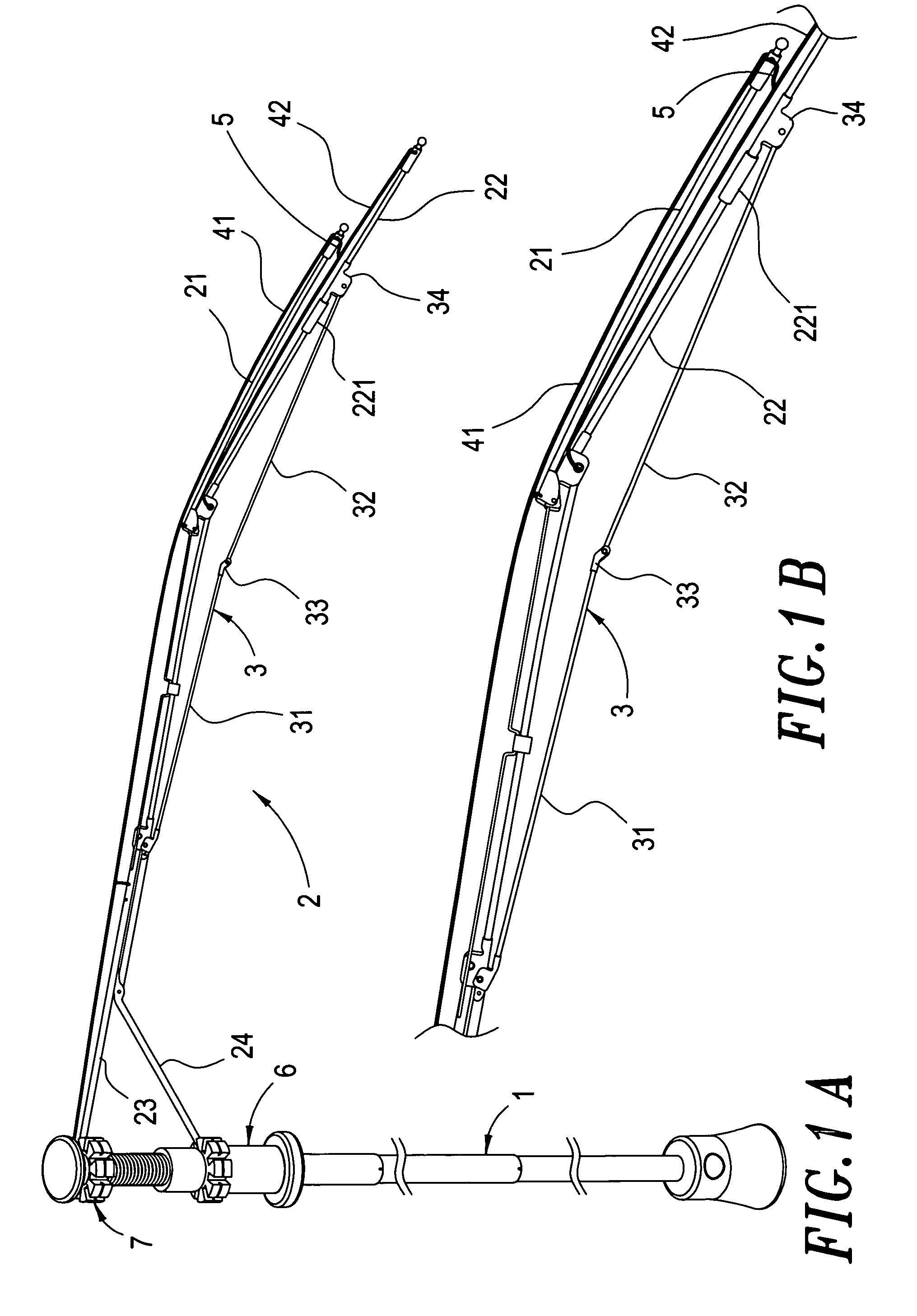
[0016] Referring to FIGS. 1A and 1B, the wind resistible umbrella of the present invention comprises a telescoping backbone 1, an upper nest 7, a lower nest 6, a plurality of multi-sectionalized main ribs 2, a plurality of auxiliary ribs 3, a first umbrella cover 41, a second umbrella cover 42, and a plurality of resilient bands.

[0017] The telescoping backbone 1 which being used to sustain the whole weight of the umbrella is formed of a plurality of telescoping tube sections.

[0018] The upper nest 7 is fixed to the cap of the umbrella on the top of the backbone 1.

[0019] The lower nest 6 is loosely sleeved over the backbone 1 to be slidably movable up and down along it.

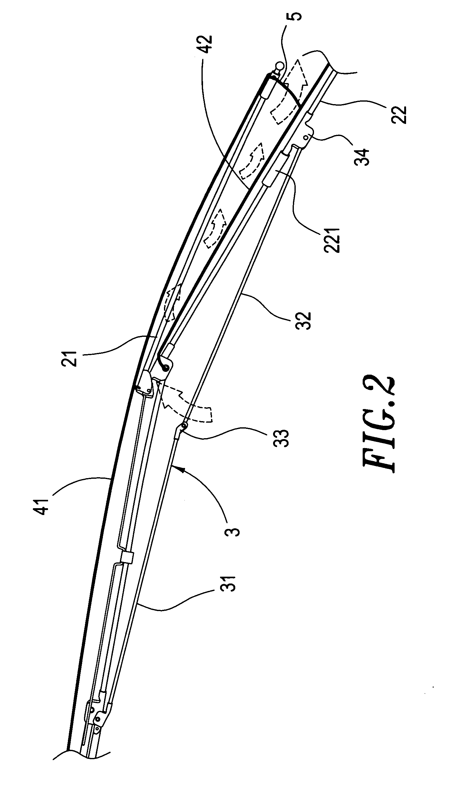
[0020] Each of the multi-sectionalized main umbrella ribs 2 is formed of several rib sections hinged together, wherein the last section is divided into unequally lengthed, almost parallelly faid first subsection 21 and second subsection 22. The former is shorter in length than the latter and is laid above the latter...


PUM


Abstract

Disclosed herein is a reinforced structure for collapsible and wind resistible umbrella comprising a telescoping backbone, an upper and a lower nests, a plurality of multi-sectionalized main umbrella ribs and auxiliary ribs, a first and a second umbrella covers, and a plurality of resilient bands. An elaborately designed jointing technique is applied to joint these main and auxiliary ribs so as to substantially reinforce the mechanical strength of the umbrella to withstand the wind force. The last section of each main rib divided into parallelly laid, shorter first subsection and longer second subsection makes it possible to lay two umbrella covers in a manner leaving a fissure therebetween so as to release the wind flowing out. Furthermore a resilient band is provided between each first subsection of the main rib and the second umbrella cover that contributes to keeping a definite separation between the first and second subsections of the main rib so as to prevent the umbrella from overturning.

Description

BACKGROUND OF THE INVENTION [0001] 1. Field of the Invention [0002] The present invention relates to a reinforced structure for collapsible and wind resistible umbrella, and more particularly, to a structure for a collapsible umbrella whose multi-sectionalized main rib has an auxiliary rib bridging between the front end of last section of the main rib and the second section of the main rib such that the umbrella is strongly structured wind resistible. [0003] 2. Description of the Prior Art [0004] An umbrella is one of the important accoutrements. In a sunny day, it may be employed as a parasol to shade harmful ultra violet ray, while in a rainy day, it is used to keep away the rain drips from the user's body so as to protect the user clean and healthy. Either the umbrella or the parasol was prevalent in bygone time, it still prevails in the present day, and surely it will be necessary in the future. [0005] There are many types of umbrellas selective in the market, such as a normal t...

Claims


Application Information

Patent Timeline
Patent Type & Authority Applications(United States)
IPC IPC(8): A45B15/00A45B25/02A45B25/22G06K9/00
CPCA45B25/22
Inventor WU, HSIEN-SAO
Owner WU HSIEN SAO
Why Eureka
Try Eureka