
Method and apparatus and program storage device for front tracking in hydraulic fracturing simulators

a program storage device and hydraulic fracturing simulator technology, applied in the field of hydraulic fracturing simulators, can solve the problems of model limitations and inability to provide very accurate results

Inactive Publication Date: 2005-10-27
SCHLUMBERGER TECH CORP
View PDF4 Cites 11 Cited by
  • Summary
  • Abstract
  • Description
  • Claims
  • Application Information

AI Technical Summary

Problems solved by technology

However, these models have limitations and do not always provide a very accurate result.
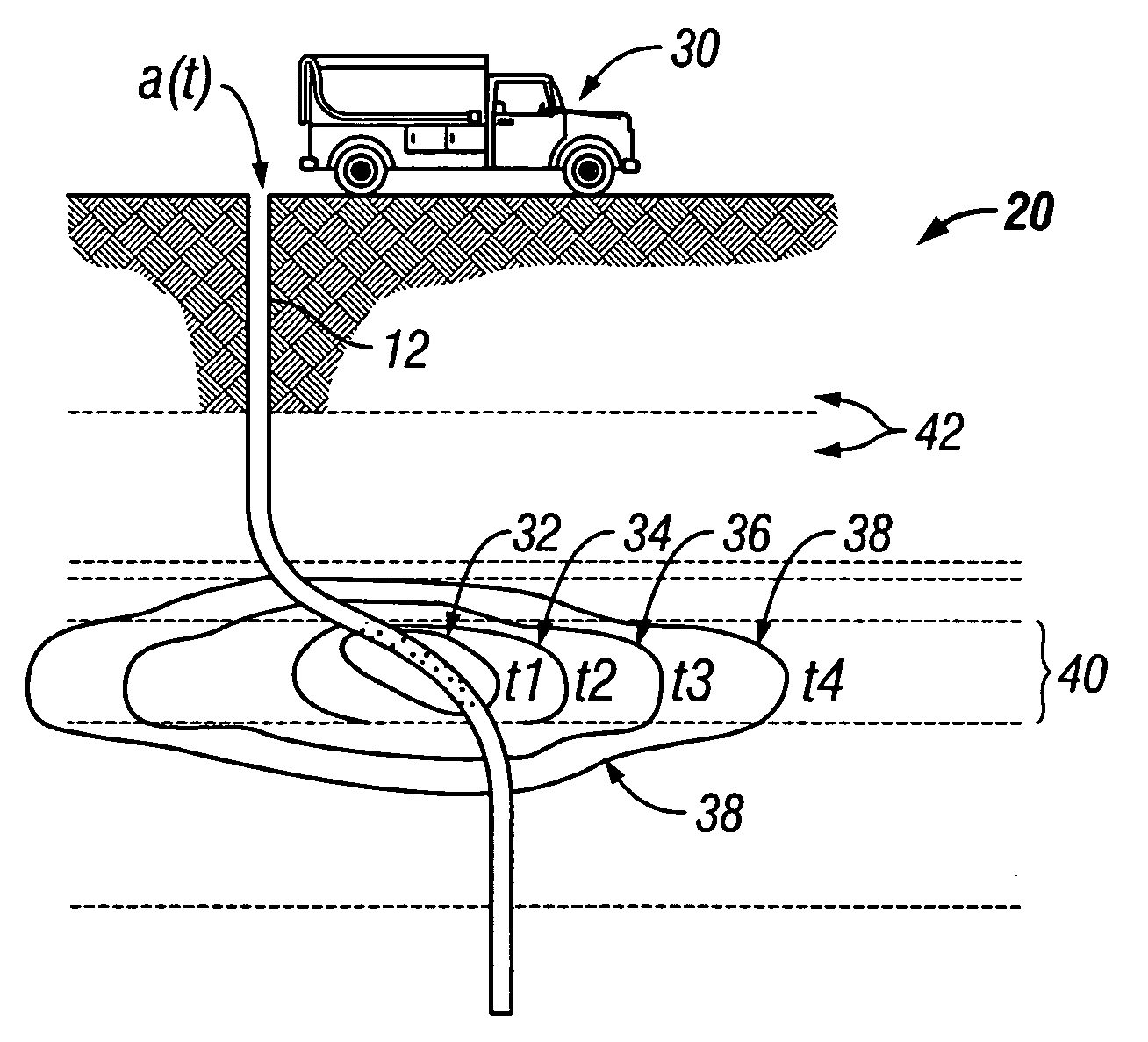
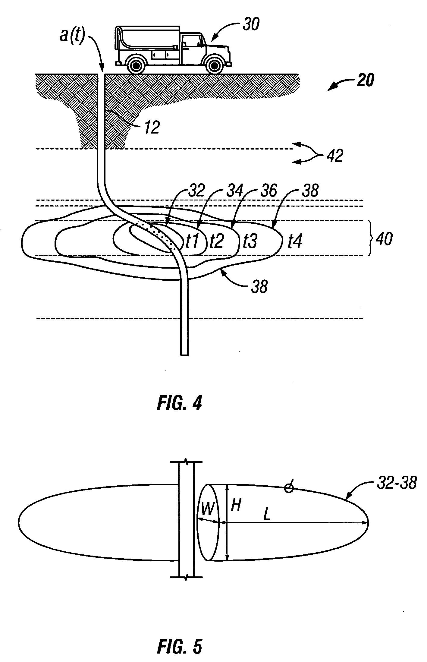
In connection with the aforementioned improvement to the ‘Volume of Fluid’ or ‘VOF’ portion of the ‘PL3D’ model of HF simulators, a key challenge to developing an effective simulator is devising a robust and accurate algorithm to locate the unknown perimeter of the fracture within the fracture plane (which is termed the ‘free boundary’).

Method used


Image

  • Method and apparatus and program storage device for front tracking in hydraulic fracturing simulators
  • Method and apparatus and program storage device for front tracking in hydraulic fracturing simulators
  • Method and apparatus and program storage device for front tracking in hydraulic fracturing simulators

Examples


first embodiment

[0117] In accordance with the present invention, the ‘VOF software’80 shown in FIGS. 17 and 18, called the ‘Full VOF’ or ‘FVOF’ approach, is executed by the processor 72a of the computer system 72 shown in FIG. 11. In FIG. 14, the ‘VOF software’80 receives, as ‘input data’, the current time, the current fill fraction, the current pressure, and the current width in each ‘tip element’50. The ‘additional steps’ practiced by the FVOF approach associated with the ‘VOF software’80 is illustrated in FIGS. 17 and 18.

[0118] In FIGS. 17 and 18, read FIGS. 17 and 18 jointly during this portion of the specification. In response to the ‘input data’ including the current time, the current fill fraction, the current pressure, and the current width in each ‘tip element’50 (that is, in response to the ‘input data’ including tk, Fk, pk, wk), a first step includes: ‘update time step’ (step 80h); do this by incrementing a previous ‘first time step’ to a ‘second time step’, where the following equation ...

second embodiment

[0122] In accordance with the present invention, the ‘VOF software’80 shown in FIGS. 15 and 16, called the ‘Marker VOF’ or ‘MVOF’ approach, is executed by the processor 72a of the computer system 72 shown in FIG. 11. In FIG. 14, the ‘VOF software’80 receives, as ‘input data’, the current time, the latest fill fraction, the current pressure, and the current width in each ‘tip element’50. The ‘additional steps’ practiced by the MVOF approach associated with the ‘VOF software’80 is illustrated in FIGS. 15 and 16.

[0123] In FIGS. 15 and 16, read FIGS. 15 and 16 jointly during this portion of the specification. In response to the ‘input data’ including the current time, the current fill fraction, the current pressure, and the current width in each ‘tip element’50 (that is, in response to the ‘input data’ including tk, Fk, pk, wk), a first step includes: ‘update time step’ (step 80a); do this by incrementing a previous ‘first time step’ to a ‘second time step’, where the following equation...


PUM


Abstract

A method and system and program storage device is adapted to continuously update a perimeter of a fracture footprint created in an Earth formation when a fracturing fluid fractures the formation penetrated by a wellbore. Two embodiments of a Volume of Fluid (VOF) software, adapted to be stored in a memory of a computer system, will locate the position of a fracture perimeter during the evolution of that fracture when the software is executed by the processor of the computer system. The two embodiments, called the ‘Marker VOF (MVOF)’ and the ‘Full VOF (FVOF)’ software, will continuously update the perimeter of the fracture footprint by updating a Fill Fraction for each tip element. The MVOF software will use a fill fraction mass balance integral equation to update the Fill Fraction for each tip element, and the FVOF software will use an integrated form of fluid flow equations to update the Fill Fraction for each tip element.

Description

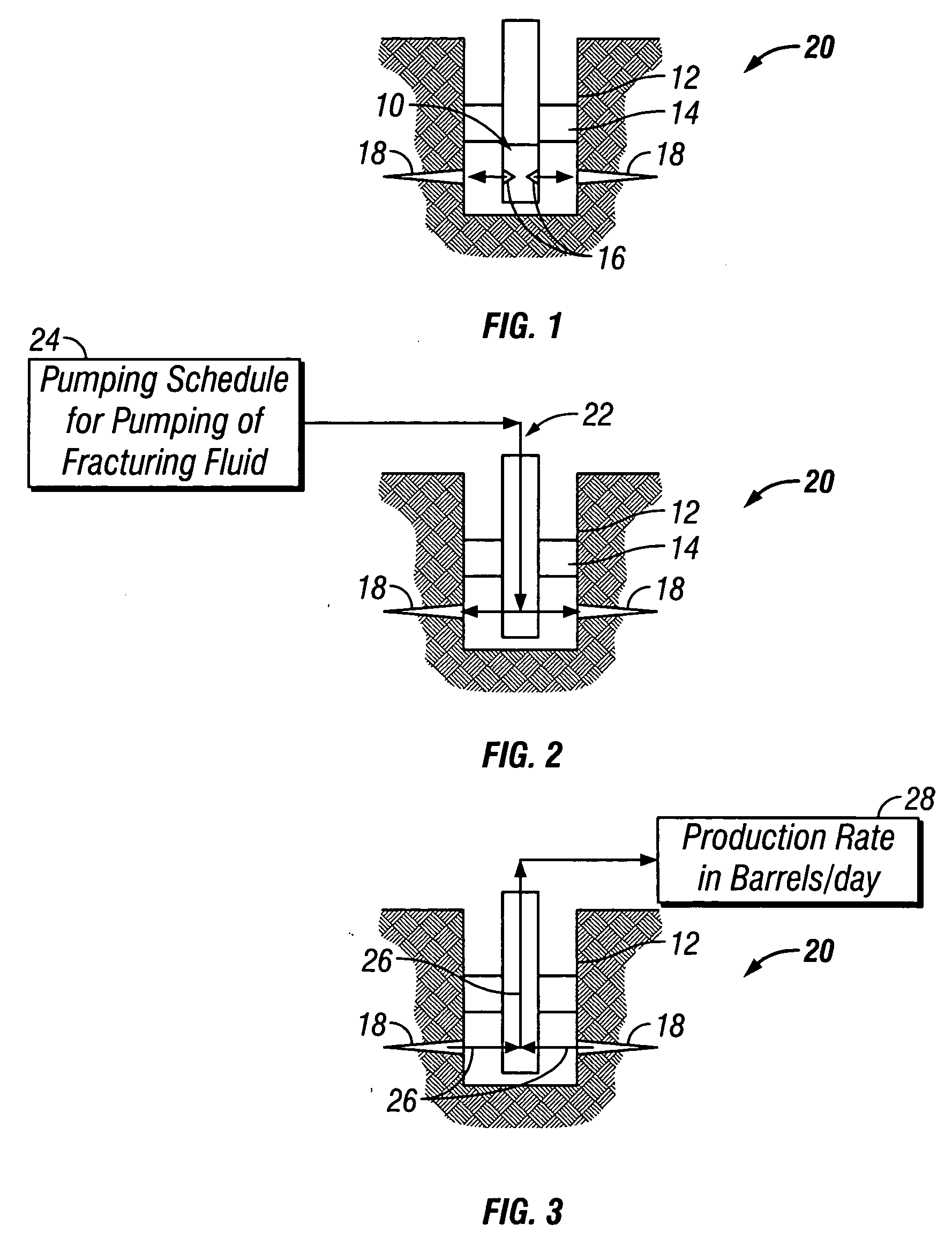
BACKGROUND OF THE INVENTION [0001] The subject matter of the present invention relates to hydraulic fracturing simulators adapted for use in the oil and gas industry, and, in particular, to a method and apparatus and program storage device for tracking of fracture fronts associated with a fracture footprint in hydraulic fracturing simulators. [0002] Hydraulic fracturing simulators are routinely used in the oil and gas industry to design hydraulic fracturing (HF) jobs, monitor them in real time, and evaluate the results to improve future HF designs. Most oil wells and many gas wells are hydraulically fractured in order that such wells will become economic and efficient producers of underground deposits of hydrocarbon. There are different classes of HF simulators available in the industry, such as PKN, KGD, Radial, P3D, and PL3D models. These models contain different levels of complexity in their governing equations and each have their own applications. For example, P3D (or pseudo 3D)...

Claims


Application Information

Patent Timeline
IPC IPC(8): E21B41/00E21B43/26E21B47/00G06F17/10G06F19/00
CPCE21B43/26
Inventor SIEBRITS, EDUARDPEIRCE, ANTHONY
Owner SCHLUMBERGER TECH CORP
Learn More