
Sanitary faucet with improved flow restriction feature and foam control feature

a flow restriction and faucet technology, applied in the field of faucets, can solve the problems of unsatisfactory foaming, unfavorable bacterial growth in the valve, and alter the taste and appearance of certain fluids, so as to reduce foam and facilitate cleaning of valve elements.

Inactive Publication Date: 2005-10-27
PERLICK CORP
View PDF7 Cites 13 Cited by
  • Summary
  • Abstract
  • Description
  • Claims
  • Application Information

AI Technical Summary

Benefits of technology

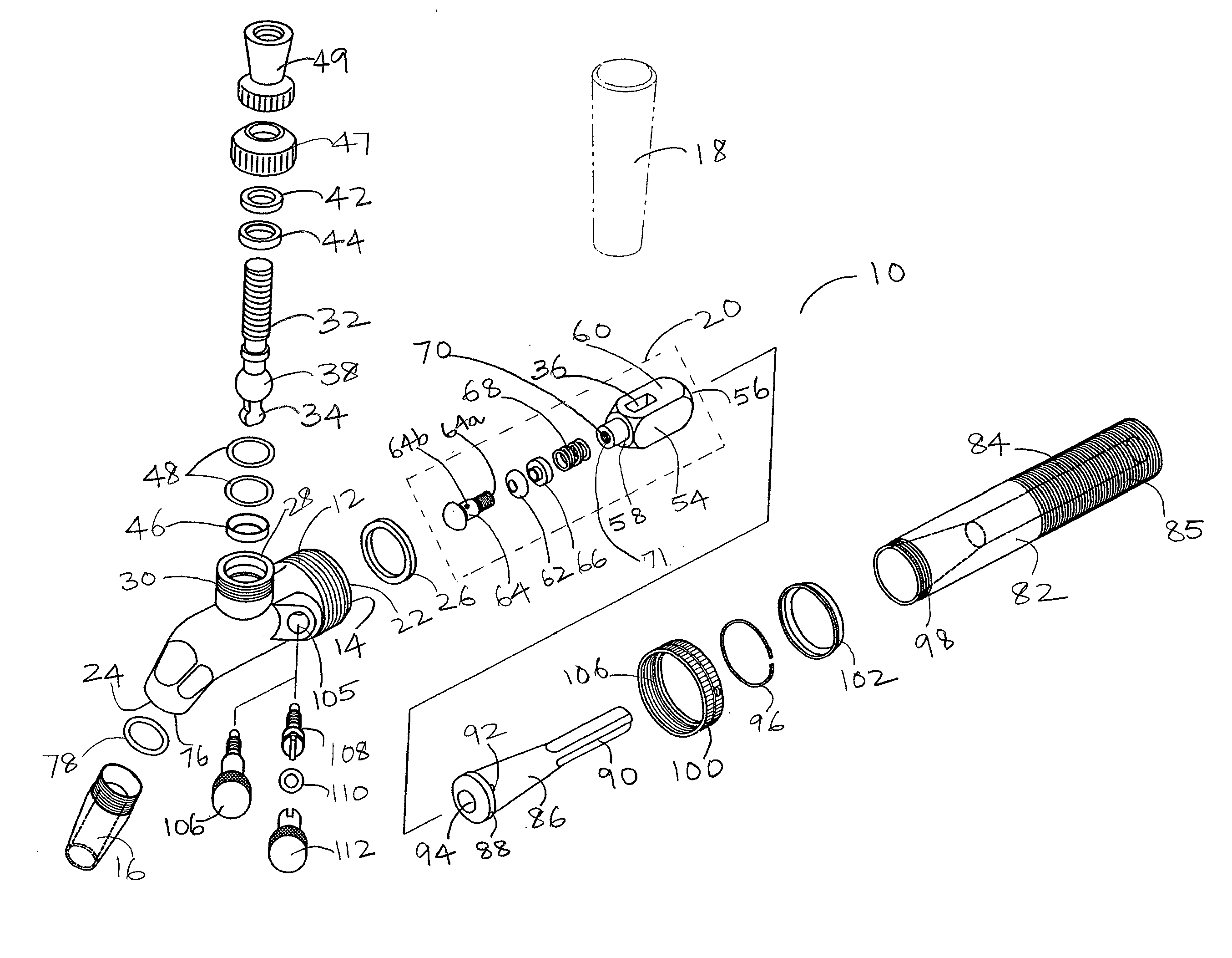
[0008] The present invention provides a sanitary dispensing faucet with a number of advantages. One advantage of the present invention is that the interior of the valve does not contain substantial amounts of air under normal usage, thereby limiting bacterial growth inside the faucet.
[0009] Another advantage of one embodiment of the present invention is a push-back foam feature, such that controlled foam may be created, when required or as desirable.
[0010] Another advantage of the present invention is a flow restrictor with a flow adjustment screw such that the pressure created by the contained fluid may be graduated and regulated at numerous levels.
[0011] Yet another advantage of the present invention is that valve elements may be cleaned efficiently without significant disassembly of the valve.
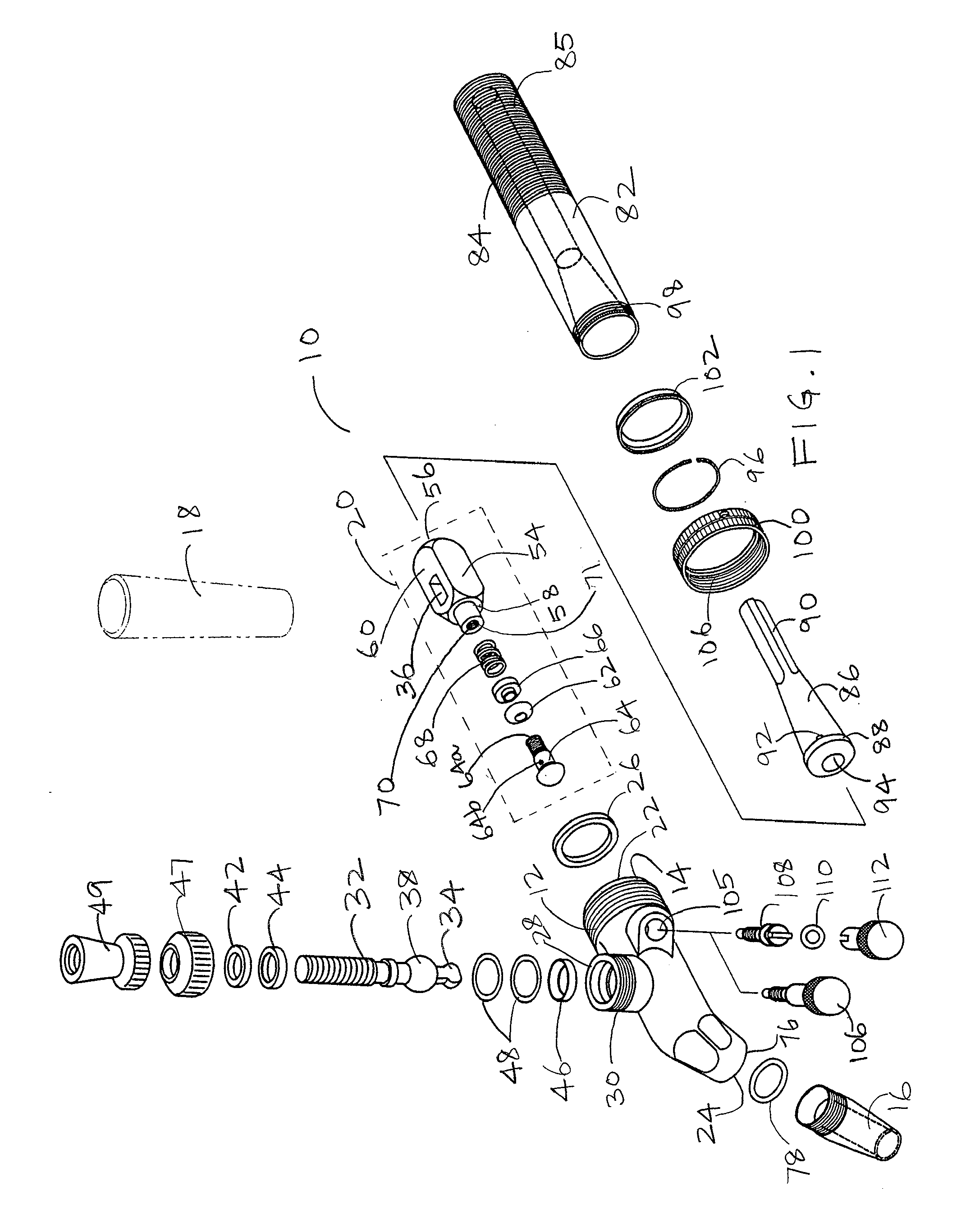
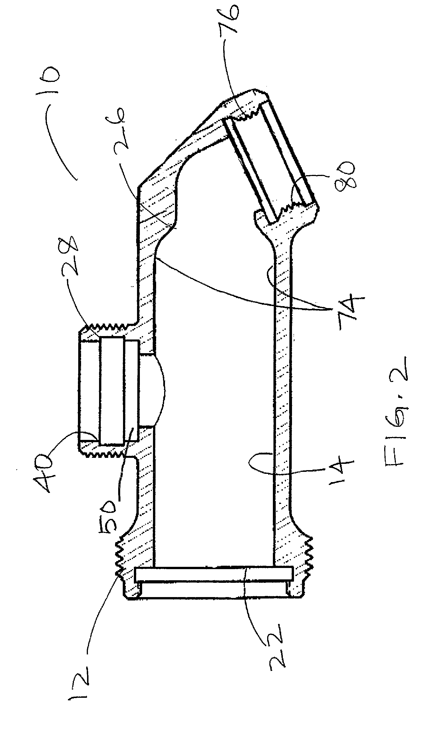
[0012] Generally the sanitary faucet includes (a) a valve body having a valve bore that has axially aligned inlet and outlet ports; (b) a plunger assembly substantially disposed in the valve body between the inlet and outlet ports; (c) a flow restrictor assembly; and (d) an adjusting screw assembly.
[0013] In one embodiment, the flow restrictor assembly includes a shank that has a first and second shank end. The first shank end is removably attached to the inlet port of the valve body, while the second shank end is removably attached to a source of the dispensing fluid. The flow restrictor assembly further includes a flow restrictor member movably disposed within the shank. The flow restrictor has a funnel head that communicates with the plunger assembly, and a fluted tail having at least one groove or channel for permitting flow of inflowing dispensing fluids from the source. In a preferred embodiment, the adjusting screw assembly regulates movement of the flow restrictor assembly within the shank.

Problems solved by technology

Standing fluid in the valve and exposure of the wet valve elements to air can give rise to undesirable bacterial growth within the valve.
Foaming however, occasionally alters the taste and appearance of certain fluids, such as beers.
Further, foaming may not be desirable when the fluid is being dispensed, but may be desirable when the fluid needs to be to topped off in a container, such as a mug.
Variation in temperature results in variation in pressure inside these kegs.
These compensator units, however, have limited control over balancing and regulating pressurized dispensing fluids.
Uncontrolled or poorly controlled pressure exerted by these fluids ultimately leads to greater wear and tear of the faucet equipment.
Also, regulating pressure via the use of compensators is not effective because these regulators may be positioned in limited orientations, resulting in limited regulation of pressure.

Method used


Image

  • Sanitary faucet with improved flow restriction feature and foam control feature
  • Sanitary faucet with improved flow restriction feature and foam control feature
  • Sanitary faucet with improved flow restriction feature and foam control feature

Examples


Embodiment Construction

[0024] A dispensing faucet is provided that is usable in any system in which a faucet is selectively operated to dispense materials from a pressurized source. For instance, it is applicable to “tapper” faucets configured to dispense beer or another pressurized liquid from a keg or another pressurized container. It is also applicable to condiment faucets configured to dispense ketchup, mustard or relish from a container. For the purposes of describing this invention, both non-viscous and viscous materials, such as beer and hot dog relish, shall be considered fluids or liquids.

[0025] The faucet comprises a valve body and a plunger which is mounted in a bore in the valve body for reciprocating movement therein. The bore has an inlet port that opens into a passage adapted for connection to a pressurized container or other source of pressurized fluid, and an outlet port that opens into a dispensing spout adapted to deliver the fluid from the faucet. A handle having a pivotable lever is ...


PUM


Abstract

A sanitary faucet with a foam control feature adaptable for dispensing pressurized fluids. The sanitary faucet includes a valve body, a plunger assembly, a flow restrictor assembly and an adjusting screw assembly. Also disclosed is a method of variably regulating fluid flow pressure and the production of foam in the sanitary faucet.

Description

CROSS REFERENCE TO RELATED APPLICATIONS [0001] The present application seeks priority from a Patent Cooperation Treaty Application PCT / US03 / 036036, which was filed on Nov. 12, 2003 with the United States Receiving Office, which in turn seeks priority from U.S. Provisional Patent Application No. 60 / 425,528 filed on Nov. 12, 2002, both of which are incorporated herein by reference in its entirety for all purposes.BACKGROUND OF INVENTION [0002] The present invention relates to faucets for use with beer tappers and other pressurized dispensers and, more particularly, relates to a sanitary flow control faucet configured to dispense materials in a regulated manner with a foam control feature. [0003] Dispensing faucets are used in a variety of applications in which materials are dispensed from pressurized containers or other pressurized sources. Dispensing faucets of this type are widely used in beverage dispensing applications in which beer, soda, or another beverage is dispensed from a p...

Claims


Application Information

Patent Timeline
Patent Type & Authority Applications(United States)
IPC IPC(8): B65D83/00B67D1/14
CPCB67D1/1466B67D1/1416
Inventor PFIEFFER, RICHARD C.KRUMBIEGEL, KARL R.STROBEL, JOHN M.
Owner PERLICK CORP
Learn More