CMOS-based receiver for communications applications

a receiver and communications technology, applied in the field of communications applications, can solve the problems of low linearity of cmos-based receivers, low cost and complexity of manufacturing bicmos-based receivers, and low noise of currently available cmos-based receivers

Inactive Publication Date: 2005-10-27
AVAGO TECH INT SALES PTE LTD
View PDF8 Cites 12 Cited by
  • Summary
  • Abstract
  • Description
  • Claims
  • Application Information

AI Technical Summary

Benefits of technology

The technical effect of this patented technology is improved reception performance by providing two receivers with different types of components for processing signals: one uses CMOS based devices or another type of component called an amplifier instead of just a single chip. This allows more precise control over how much power each part works but also reduces interference from other parts around it.

Problems solved by technology

The technical problem addressed in this patent text is the need for new CMOS-based devices that have higher sensitivity, lower noise, and higher degrees of linearity than currently available systems. The text also discusses methods for manufacturing and operating such devices.

Method used


Image

  • CMOS-based receiver for communications applications
  • CMOS-based receiver for communications applications
  • CMOS-based receiver for communications applications

Examples


Embodiment Construction

)

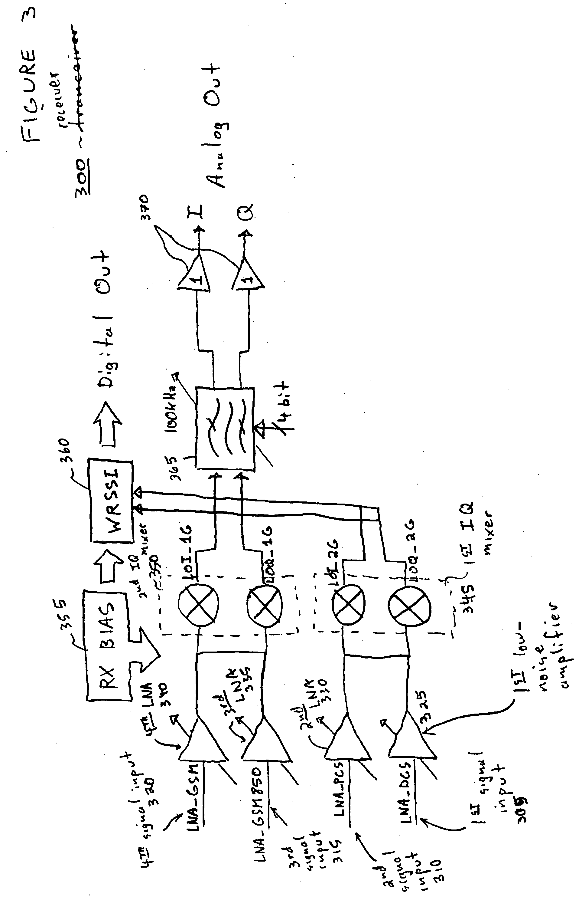
[0026]FIG. 3 illustrates a block diagram of a representative receiver 300 according to certain embodiments of the present invention. It should be noted that any or all of the components included in the block diagram may be differential, including the inputs to the amplifiers discussed below.

[0027] The representative receiver 300 includes a front end region that includes four signal inputs 305, 310, 315, 320, four low-noise amplifiers (LNAs) 325, 330, 335, 340, and two IQ mixers 345, 350. Representative receiver 300 also includes receiver (RX) bias 355, Wide-Band Received Signal Strength Indicator (WRSSI) circuit 360, filter 365, and amplifiers 370. One skilled in the art of the present invention will appreciate that receivers, transceivers, and other devices according to certain embodiments of the present invention may include components other than those illustrated in FIG. 3. Also, one skilled in the are will appreciate that one or more of the components illustrated in FIG. 3 may...


PUM


Abstract

A receiver and receiver front end having multiple independent differential inputs, multiple independent differential low-noise amplifiers, and two sets of double-balanced IQ mixers. The double-balanced mixers include cross-coupled PMOS devices that dynamically inject current at zero-crossing points to cancel out tail currents in the mixers. Also, methods of operating the above-discussed receiver and receiver front end.

Description


Claims


Application Information

Patent Timeline
Owner AVAGO TECH INT SALES PTE LTD
Why Eureka
Try Eureka