
Health monitoring method and system for a permanent magnet device

a permanent magnet and monitoring method technology, applied in the direction of testing/monitoring control systems, process and machine control, instruments, etc., can solve the problems of inability to use large engines, all electric motors are prone to common failure modes, and permanent magnet motors are also prone to performance degradation

Active Publication Date: 2005-10-27
HAMILTON SUNDSTRAND CORP
View PDF12 Cites 19 Cited by
  • Summary
  • Abstract
  • Description
  • Claims
  • Application Information

AI Technical Summary

Benefits of technology

[0008] By providing periodic monitoring of motor performance, the invention detects differences in the implied output torque capability of the motor before it reaches an unacceptable level. Thus, it is possible to notify users of a pending motor fault before an actual fault occurs, allowing the user to response pro-actively without waiting for the motor to actually fail before addressing motor problems. As a result, the invention makes it possible to use high-torque permanent magnet motors in applications, such as electric starting, where reliability is one of the critical parameters.

Problems solved by technology

Electric starters are known for starting small engines, but the special requirements of large engines have generally made them inappropriate for use with large engines.
One of the challenges in designing electric starters is to create a high-performance unit with minimal (packaging) size and total weight.
All electric motors are prone to common failure modes, such as broken or shorted wires.
However, despite their high performance density, permanent magnet motors are also prone to performance degradation resulting from demagnetization of the magnets due to, for example, excessive environmental temperatures.
Depending on the degree of failure, many of these degradations are not detectable and may result in operational failures or, in extreme cases, generation of excessive heat that may ignite or melt the starter components.

Method used


Image

  • Health monitoring method and system for a permanent magnet device
  • Health monitoring method and system for a permanent magnet device
  • Health monitoring method and system for a permanent magnet device

Examples


Embodiment Construction

[0015] Generally, the invention makes electric devices, and magnetic motors or generators in particular, more suitable for critical applications by incorporating a monitoring system that checks the health of the motor based on its output characteristics.

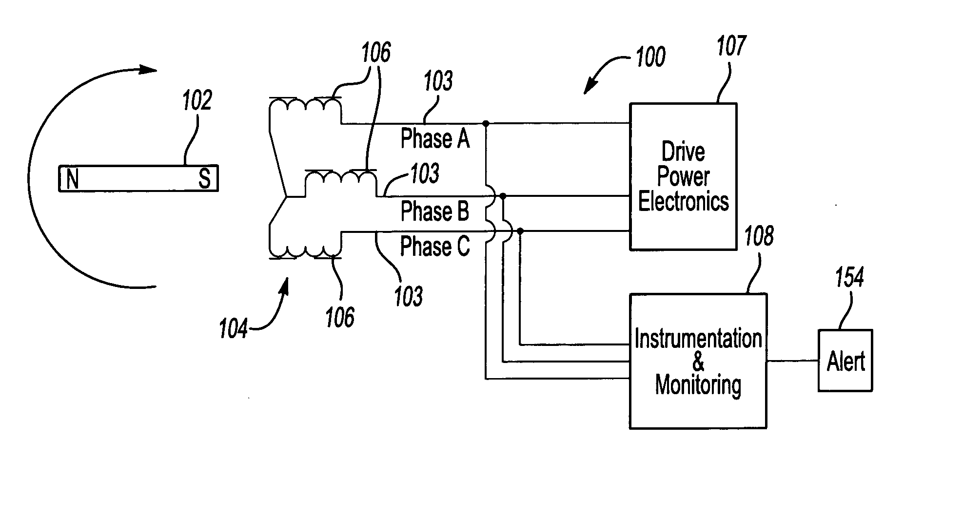
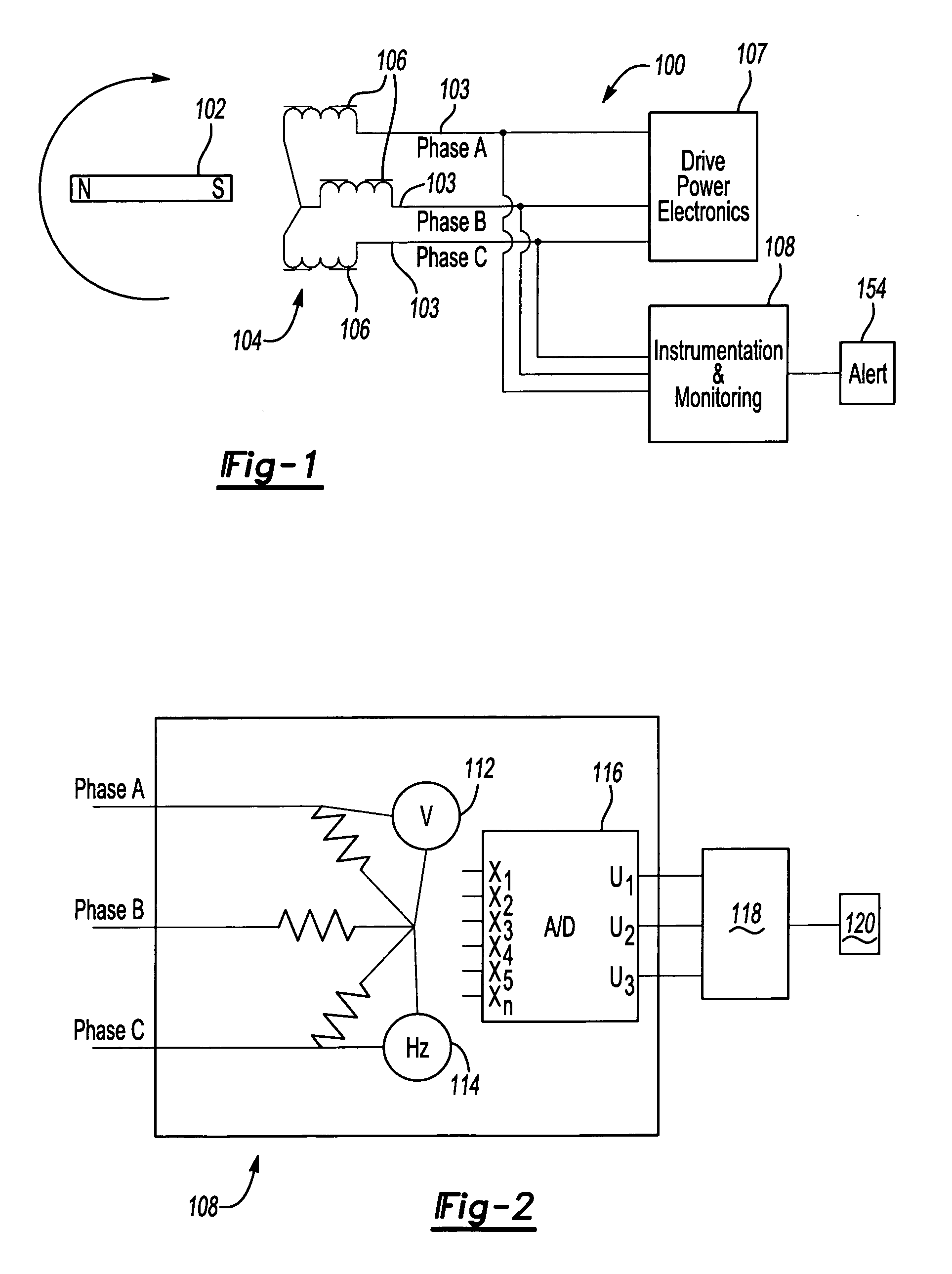
[0016]FIG. 1 is a schematic diagram of a magnetic motor 100 whose operation can be monitored according to the invention. Note that FIGS. 1 and 2 are simplified for illustrative purposes and show only one pole of a multiple-pole device. The motor 100 includes a magnetic rotor 102, which is a permanent magnet, that rotates within a stator 104 having three phases A, B and C with corresponding coil windings 106. As is known in the art, drive power electronics 107 control the current moving through the windings 106 to control the magnetic field surrounding the windings 106, causing the magnetic rotor 102 to rotate as it repels and attracts the poles in the generated magnetic field.

[0017]FIG. 2 illustrates a wye-connected motor. As shown...


PUM


Abstract

A method and system for monitoring the performance of a permanent magnet device, such as a motor or generator, and providing early detection of motor performance deterioration. The back electromotive force (EMF) of the motor is measured at selected conditions when the motor is in a normal healthy condition to obtain a reference signature response. A measured signature is then obtained periodically during the life of the motor at the same conditions as the reference signature to check the current back EMF characteristic of the motor. If the measured signature deviates from the reference signature by a predetermined threshold, it indicates that the motor performance has degraded to a condition requiring attention.

Description

TECHNICAL FIELD [0001] The present invention is directed to monitoring operation of an electrical device, and more particularly to a method and system that checks the health of a permanent magnet device, such as a motor or generator. BACKGROUND OF THE INVENTION [0002] Large-scale power generators often use gas turbine engines to supply power to a geographic region. Reliable start up of these engines is critical to ensure that power outages do not occur. [0003] Electric starters are known for starting small engines, but the special requirements of large engines have generally made them inappropriate for use with large engines. Many gas turbines in the 20 to 50 MW range are derivatives of aircraft engines (known as “aeroderivatives” and, as such, they initially retained the lightweight, high-performance pneumatic starters from the initial design. As applications evolved, the pneumatic starters were replaced with hydraulic starters because weight is less of a concern in ground-based ga...

Claims


Application Information

Patent Timeline
IPC IPC(8): G01R31/34
CPCG01R31/343
Inventor GUSTAFSON, JAMES R.SHAH, MAHESH J.
Owner HAMILTON SUNDSTRAND CORP
Learn More