Hybrid Gas Turbine Propulsion System

a gas turbine and hybrid technology, applied in the field of hybrid gas turbine propulsion systems, can solve the problems of inordinately high fuel consumption, inability to fully exploit the thermodynamic energy potential of typical aviation fuels, and failure of high-stressed power turbine rotating machinery, so as to avoid thermal stress, reduce fuel consumption, and increase responsiveness to sudden throttle inputs

Active Publication Date: 2015-01-15
SHELLEY RUDOLPH ALLEN
View PDF3 Cites 116 Cited by
  • Summary
  • Abstract
  • Description
  • Claims
  • Application Information

AI Technical Summary

Benefits of technology

[0006]The invention seeks to significantly lower fuel consumption. Higher responsiveness to sudden throttle inputs and modularity in components that can be isolated separately within an aircraft / vehicle structure for safety and weight / balance considerations, as well as avoidance of thermal stresses on post-combustion gas turbine rotating machinery, are the highlighted characteristics of the invention.

Problems solved by technology

Inherent limitations to gas turbine power section rotating machinery vis-à-vis thermal stress inhibiting higher combustion temperatures and thus limiting fuel efficiency force designers to adopt complex mechanical interventions to achieve higher thrust potential, e.g., high-bypass turbofan disks, while leaving nearly half of the thermodynamic energy potential available from typical aviation fuels unexploited because burning them at their highest stoichiometric combustion temperatures would cause highly-stressed power turbine rotating machinery to fail.
Inordinately high fuel consumption is also expended while aircraft are ground taxiing on main engine power, idling, or left at low-output settings such as when throttled back on descent-to-landing phases of aircraft operations.
A solution to the thermal stress problem in gas turbine engines is still elusive and pertinent, given the cost of aviation jet fuel that is now impacting commercial airline financial solvency and air travel affordability, such that the adversely high low-power setting fuel consumption of said engines also needs to be solved.
In all said prior art, they did not address excessively high fuel consumption when powering a turbocompressor over extended periods at high altitudes using the devices they taught, given limitations to those devices taught while used in the stratosphere, or flexibility over a wide range of altitudes, or any means to ameliorate excessive fuel consumption when gas turbines as they taught are throttled back during descent and landing phases of a flight, or on the ground during taxiing maneuvers, when queuing for an active runway or idling after engine start.
Ram air turbines (RAT) as mentioned by Brewer and Giles are conventionally simple, small, retractable devices that lack the flexibility to contribute significantly to the creation of propulsion throughout a flight mission at varying altitudes, speeds and configurations.
Said art does not entertain powering the compressor work of a large main driver engine as used by commercial transport aircraft.
No design feature was offered to improve fuel efficiency for said engines at various speeds and altitudes.
Conventional aviation turboshaft-powered auxiliary power units (APU) as mentioned in prior art, being generator sets as typically installed on jet aircraft of today, do not provide power levels sufficient to electrically drive the turbocompressors of the main turbojet / turbofan driver engines on any given size category of jet aircraft on which they are installed.

Method used


Image

  • Hybrid Gas Turbine Propulsion System
  • Hybrid Gas Turbine Propulsion System
  • Hybrid Gas Turbine Propulsion System

Examples


Embodiment Construction

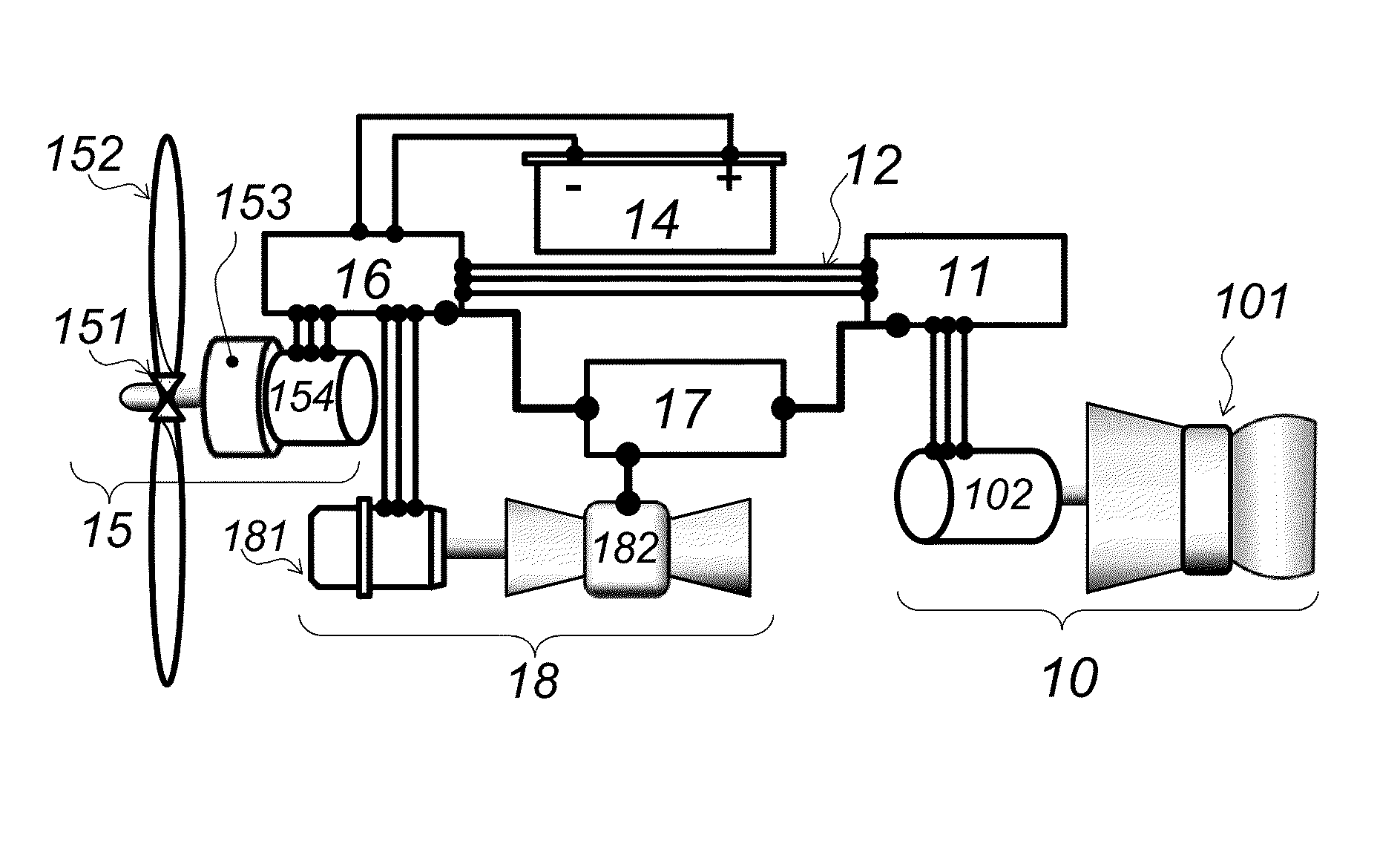
[0017]In FIG. 1, the hybrid aerodynamic thrust system is schematically depicted, wherein, an aircraft at rest uses electrical energy from the SE module 14, to power aircraft electrical systems, as well as supply the APU module 18 with start-up current. Three-phase AC main bus current is expected in the preferred embodiment. A minimum electric current operating frequency should be the aviation standard 400 Hz for high-tension devices, or higher, to achieve practical size and weight specifications for the electric motors, motor / generators and stand-alone generators used within this invention. However, electrical system specifications regarding specific voltages, loadings or specific electric motor, generator or motor / generator unit designs are not the subject of this disclosure since existing art covers said design and construction adequately.

[0018]In a typical aircraft flight mission, after the APU 18 has been started, it can then drive the TT module turbocompressor(s) 102a, 102b and...


PUM


Abstract

A hybrid aerodynamic thrust system as a prime mover for aircraft or other high-speed vehicles. An arrangement of dual thrust resources to alternately accommodate low and high airspeed regimes. Electromotive force is used in lieu of hot section power turbines to achieve engine air compression or alternately perform thrust work at low velocities.

Description

CROSS-REFERENCE TO RELATED APPLICATIONS[0001]This is a continuation-in-part of application Ser. No. 12 / 950,859, filed Nov. 19, 2010, now abandoned. Related patents in prior art include:4,368,620Jan. 18, 1983Giles4,051,671Oct. 4, 1977Brewer3,678,306Jul. 18, 1972Garnier et al.BACKGROUND OF THE INVENTION[0002]Inherent limitations to gas turbine power section rotating machinery vis-à-vis thermal stress inhibiting higher combustion temperatures and thus limiting fuel efficiency force designers to adopt complex mechanical interventions to achieve higher thrust potential, e.g., high-bypass turbofan disks, while leaving nearly half of the thermodynamic energy potential available from typical aviation fuels unexploited because burning them at their highest stoichiometric combustion temperatures would cause highly-stressed power turbine rotating machinery to fail. Inordinately high fuel consumption is also expended while aircraft are ground taxiing on main engine power, idling, or left at low...

Claims


Application Information

Patent Timeline
Patent Type & Authority Applications(United States)
IPC IPC(8): F02K5/00F02C3/32
CPCF02C3/32F02K5/00B64D27/10B64D27/12B64D27/14B64D31/04B64D2027/026F01D15/10F02C7/32F02K3/06F05D2220/34Y02T50/60Y02T50/40
Inventor SHELLEY, RUDOLPH ALLEN
Owner SHELLEY RUDOLPH ALLEN
Why Eureka
Try Eureka