A pipe coupling detection device

A detection device and pipeline technology, applied in construction and other directions, can solve problems such as misjudgment of pipeline couplings and inability to achieve accurate guidance in logging operations, and achieve the effect of improving accuracy and avoiding misjudgment of pipeline couplings

Active Publication Date: 2017-10-27
YANTAI JEREH PETROLEUM EQUIP & TECH CO LTD
View PDF9 Cites 112 Cited by
  • Summary
  • Abstract
  • Description
  • Claims
  • Application Information

AI Technical Summary

Problems solved by technology

[0005] At present, there are mainly two ways to grasp the position of the coupling during the operation of the tubing. One way is to estimate the position of the coupling through manual visual inspection and experience. However, this method is prone to failure due to worker fatigue or operator error. lead to the occurrence of safety accidents; another way is to use the oil pipe coupling detection device for detection. The oil pipe coupling detection device usually includes an excitation coil and a detection coil used in conjunction with the excitation coil. , so when the oil pipe and the pipe coupling pass through the detection coil, the change of the induced electromotive force in the detection coil is different, so as to distinguish the oil pipe and the pipeline; If the hoop passes through, and when the tubing shakes or there are impurities such as oil, the change in the electromotive force in the detection coil may be the same as that of the hoop, which is prone to misjudgment and cannot be used for oil well workover or logging operations. achieve precise guidance
[0006] Therefore, how to avoid the misjudgment of the coupling caused by the sloshing of the pipeline is a technical problem that those skilled in the art need to solve urgently.

Method used


Image

  • A pipe coupling detection device

Examples


Embodiment Construction

[0022] The core of the present invention is to provide a pipeline coupling detection device, so as to avoid misjudgment of the position of the pipeline coupling due to the sloshing of the pipeline, and improve the accuracy of pipeline coupling detection.

[0023] In order to enable those skilled in the art to better understand the solution of the present invention, the present invention will be further described in detail below in conjunction with the accompanying drawings and specific embodiments.

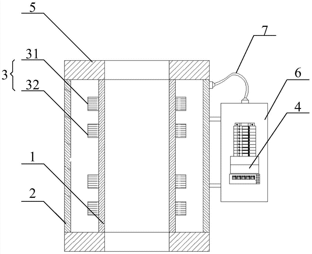
[0024] Please also refer to figure 1 , figure 1 It is a structural schematic diagram of a pipeline coupling detection device disclosed in an embodiment of the present invention.

[0025] The pipeline coupling detection device provided by the embodiment of the present invention is mainly used in the oil pipe lifting operation in the workover or logging process. The pipeline coupling detection device includes an inner layer pipe 1 and an outer layer pipe 2. The inner layer pipe 1 ...


PUM


Abstract

The invention relates to a pipeline coupling detection device, which comprises an inner layer pipe, an outer layer pipe, a plurality of sets of detection assemblies and a data processor, wherein a pipeline and a pipeline coupling can penetrate through the inner layer pipe; the outer layer pipe sleeves the outside of the inner layer pipe; an annular mounting cavity is formed between the inner layer pipe and the outer layer pipe; the plurality of sets of detection assemblies are wound on the inner layer pipe at intervals, and are located in the annular mounting cavity; each detection assembly comprises a magnet exciting coil and a detection coil; the data processor is connected with the detection coils and is used for comparing induced electromotive force difference values in different detection coils; a preset difference value is stored in the data processor; and the data processor sends out a coupling signal only when the induced electromotive force difference value in any two detection coils is greater than or equal to the preset difference value. According to the pipeline coupling detection device, pipeline coupling misjudgment caused by pipeline shaking can be effectively avoided.

Description

technical field [0001] The invention relates to the technical field of oil field workover and well logging, in particular to a pipeline collar detection device used in the well workover and well logging process. Background technique [0002] Snubbing technology is currently being used more and more in domestic oil fields. Its main advantages are that it can protect and maintain the original productivity of the formation, reduce the number of stimulation measures such as acidizing and fracturing, and provide long-term development and stable production for oil and gas fields. good foundation. [0003] The so-called snubbing technology specifically refers to a method of forced operation without blowout or snubbing when there is pressure in the well. It is mainly used for oil and gas well operations, maintenance of water injection wells, etc. [0004] In the process of oil field workover, under the condition of pressure, the tubing must be continuously lifted and lowered. When ...

Claims


Application Information

Patent Timeline
Patent Type & Authority Patents(China)
IPC IPC(8): E21B47/092
CPCE21B47/092
Inventor 张树立王洪力孙任伯邹昌海杨丽丽
Owner YANTAI JEREH PETROLEUM EQUIP & TECH CO LTD
Why Eureka
Try Eureka