Display driving circuit and driving method thereof

a technology of display driving and driving circuit, which is applied in the direction of electric digital data processing, instruments, computing, etc., can solve the problems of difficult circuit scaling down, signal interference between signal lines, and bad influence on circuit operation, so as to reduce the number of signal lines, reduce interference, and reduce the area occupied by signal lines

Active Publication Date: 2005-10-27
MAGNACHIP SEMICONDUCTOR LTD
View PDF3 Cites 3 Cited by
  • Summary
  • Abstract
  • Description
  • Claims
  • Application Information

AI Technical Summary

Benefits of technology

[0010] It is, therefore, an object of the present invention to provide a technology that can reduce the number of signal lines by encoding a PWM signal used to implements a gradation display function in a display driver IC, thereby reducing an area occupied by the signal lines and reducing an interference between the signal lines.

Problems solved by technology

Also, signal interference often occurs between the signal lines.
Therefore, if the circuit is badly designed, it may have a bad influence on the operation of the circuit.
Accordingly, the signal lines occupy a wide area in the entire IC and it is difficult to scale down the circuit.

Method used


Image

  • Display driving circuit and driving method thereof
  • Display driving circuit and driving method thereof
  • Display driving circuit and driving method thereof

Examples


Embodiment Construction

[0028] Hereinafter, the present invention will be described in detail with reference to the accompanying drawings.

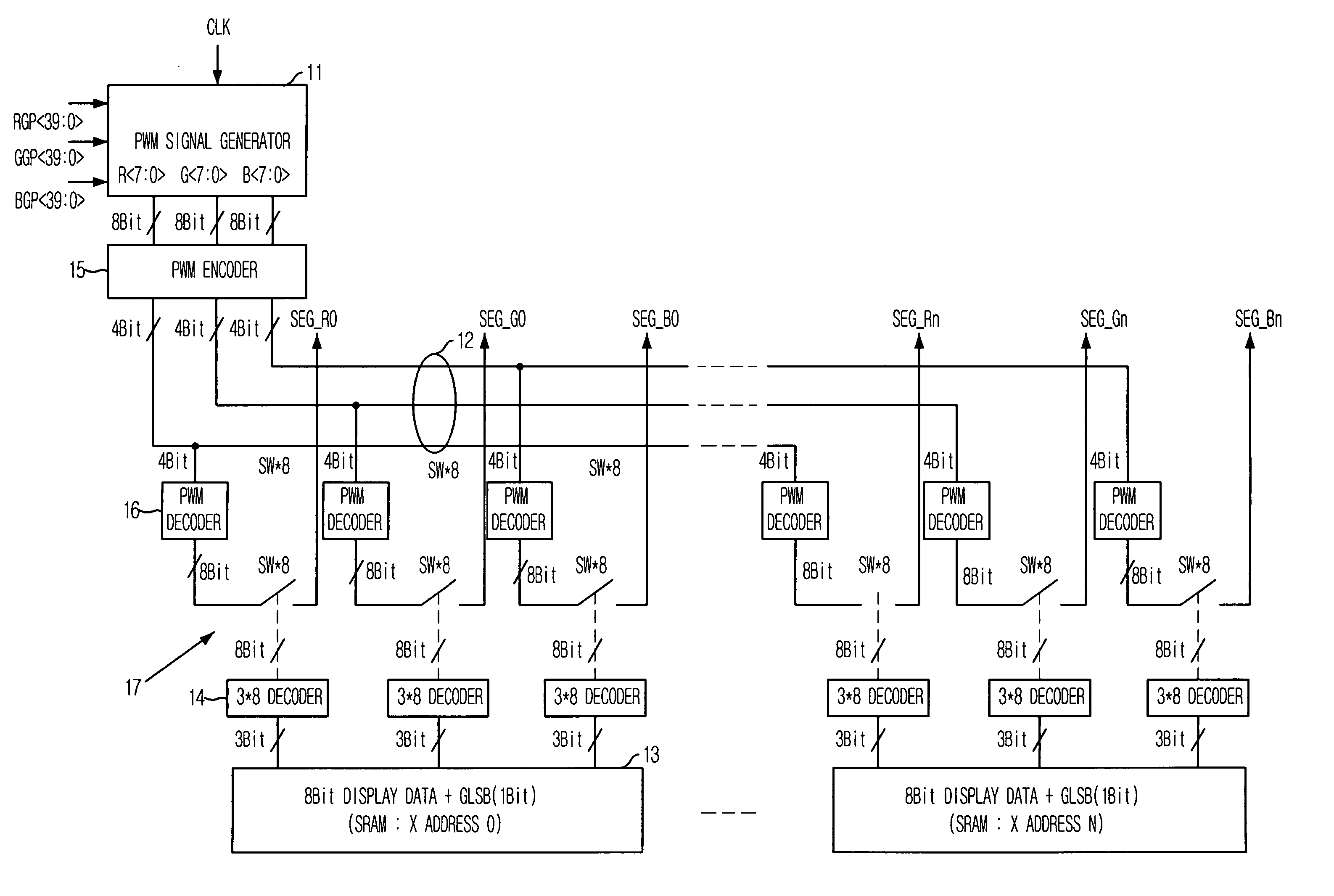
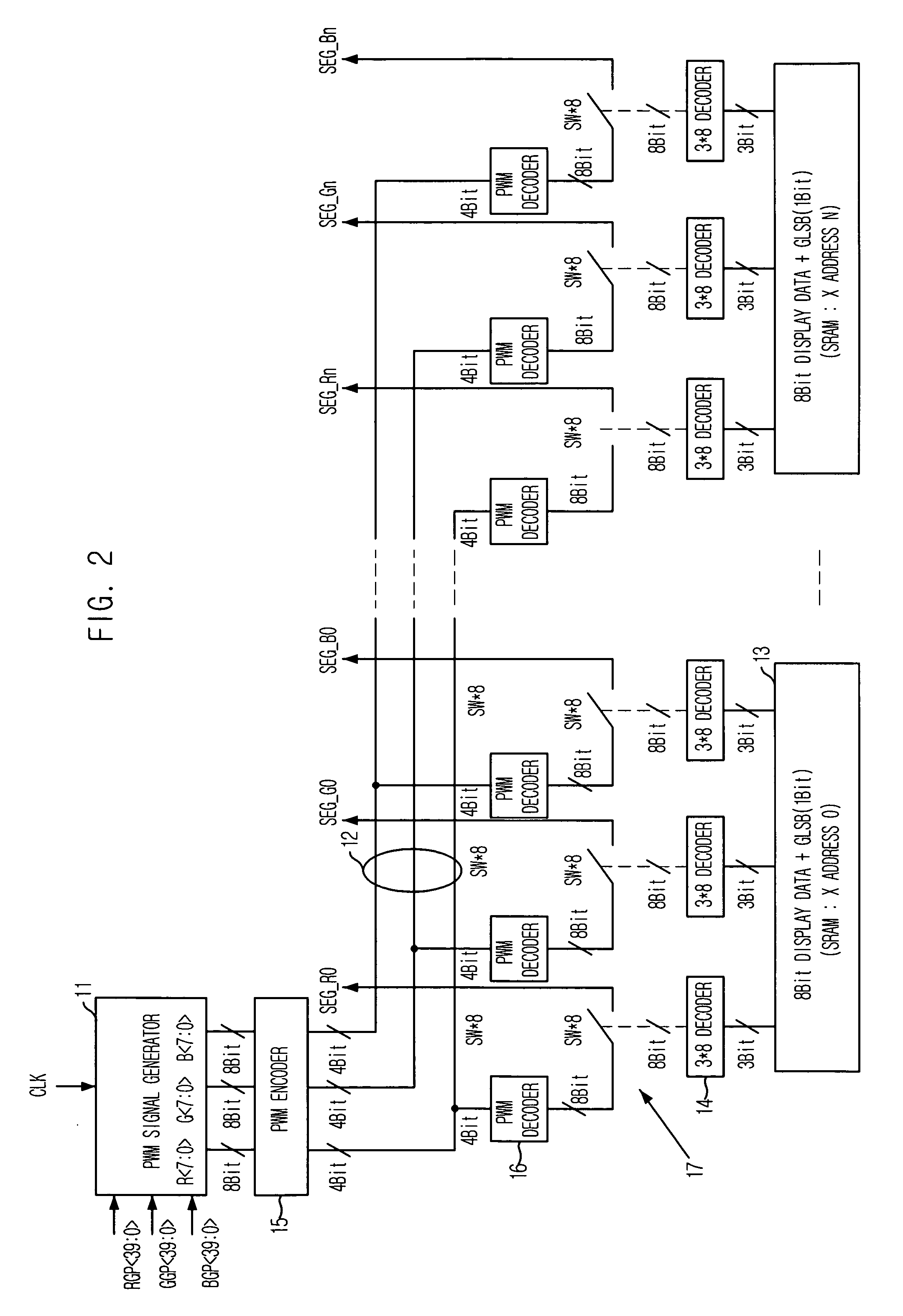
[0029]FIG. 2 is a circuit diagram of a display driver IC in accordance with a preferred embodiment of the present invention.

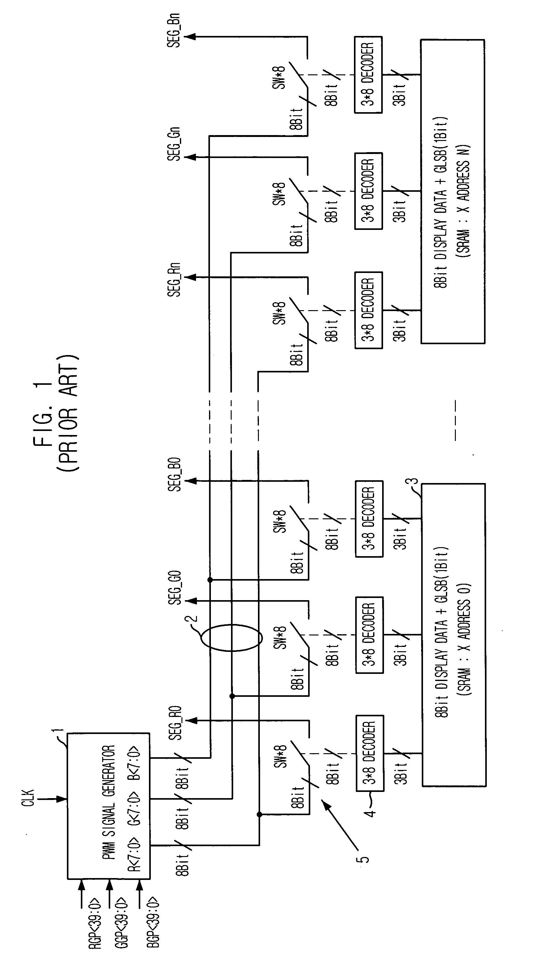
[0030] A basic structure of the circuit shown in FIG. 2 is similar to that of the conventional circuit shown in FIG. 1. That is, PWM signals are generated from a PWM signal generator 11 so as to represent the gradation and are transmitted to an entire system along PWM signal lines 12. Switches 17 are turned on / off by an SRAM decoder 14, based on display data stored in an SRAM. In this manner, the transmission of the PWM signals is controlled.

[0031] However, the display driver IC further includes a PWM encoder 15 and a PWM decoder 16 on a signal path directed from the PWM signal generator 11 and thus the number of the PWM signal lines 12 is reduced.

[0032] In FIG. 2, the number of the PWM signal lines is 12 (=3×4). Compared with the 24 (=3×8) sign...


PUM

PropertyMeasurementUnit
widthaaaaaaaaaa
widthsaaaaaaaaaa
pulse widthaaaaaaaaaa

Abstract

There is provided a technology that can reduce the number of signal lines by encoding a PWM signal used in a display driver IC. The display driver circuit for displaying a gradation on a display screen based on a PWM signal includes a PWM signal generator for generating a PWM signal, a PWM encoder for encoding the PWM signal generated from the PWM signal generator, a PWM decoder for decoding the encoded PWM signal into the PWM signal, a switching unit for selectively outputting the PWM signal generated from the PWM decoder, a data storage unit for storing a display data used to switch the switching unit, and an SRAM decoder for outputting an on/off signal to the switching unit according to the display data outputted from the data storage unit.

Description

FIELD OF THE INVENTION [0001] The present invention relates to a driver circuit for driving a display screen in a liquid crystal display (LCD) or the like; and, more particularly, to a technology that can reduce the number of signal lines by encoding a pulse width modulation (PWM) signal used to implement a gradation display function in a display driver integrated circuit (IC). DESCRIPTION OF RELATED ART [0002] In driving a liquid crystal display (LCD) or the like, an active addressing technology is recently used to display an image having a plurality of gradation levels. A representative method is a Frame Rate Control (FRC) method, a Pulse Width Modulation (PWM) method, and an Amplitude Modulation (AM) method. [0003]FIG. 1 illustrates a structure of a circuit used to display a PWM-based gradation in a conventional 256-color LCD driver integrated circuit (IC) having a PWM gradation display function. [0004] Referring to FIG. 1, PWM signals generated from a PWM generator 1 are transmi...

Claims


Application Information

Patent Timeline
Patent Type & Authority Applications(United States)
IPC IPC(8): G02F1/133G09G3/20G09G3/36G09G5/10
CPCG09G3/3685G09G3/2014A47J37/0763A47J37/0786A47J2037/0777A47J2037/0795
Inventor LEE, YONG-SUP
Owner MAGNACHIP SEMICONDUCTOR LTD
Why Eureka
Try Eureka