Flashlight with detented rotary control

Active Publication Date: 2005-10-27
SUREFIRE LLC
View PDF4 Cites 90 Cited by
  • Summary
  • Abstract
  • Description
  • Claims
  • Application Information

AI Technical Summary

Benefits of technology

[0016] The present invention overcomes the limitations of the prior art by providing a flashlight has a lamp assembly with a number of different output states. The flashlight has an elongated housing defining a housing axis, and a control ring encompasses the housing and rotates on the housing axis. The control ring operates to change th

Problems solved by technology

The principal light source used in flashlights is the tungsten filament lamp, as alternatives suffered inadequate illumination, or excessive battery consumption.
Tungsten filament lamps, however, cannot be effectively used as a variable output light source because they must be operated close to their design point (current & voltage) if they are to retain their efficiency in converting electrical energy to light.
While effective, such dual-source lights have several limitations.
First, they require the user either to maintain button pressure throughout illumination, or to rotate a switch between operating modes.
This requires either continuous use of one hand, or the occasional use of both hands (to rotate the switch), either of which may be disadvantageous for critical military and law enforcement applications.
When set to certain switch modes existing lights do not enable rapid illumination for emergencies.
Changing modes takes time, and requires two hands, which may be disadvantageous in an emergency.
Existing lights have limited choice of light levels.
Moreover, there is a substantial range of possibly desired brightness levels between the maximum of the first lamp and the full brightness of the second lamp that are not obtainable.
Such lights provide different

Method used


Image

  • Flashlight with detented rotary control
  • Flashlight with detented rotary control
  • Flashlight with detented rotary control

Examples


embodiment

Variable Color Embodiment

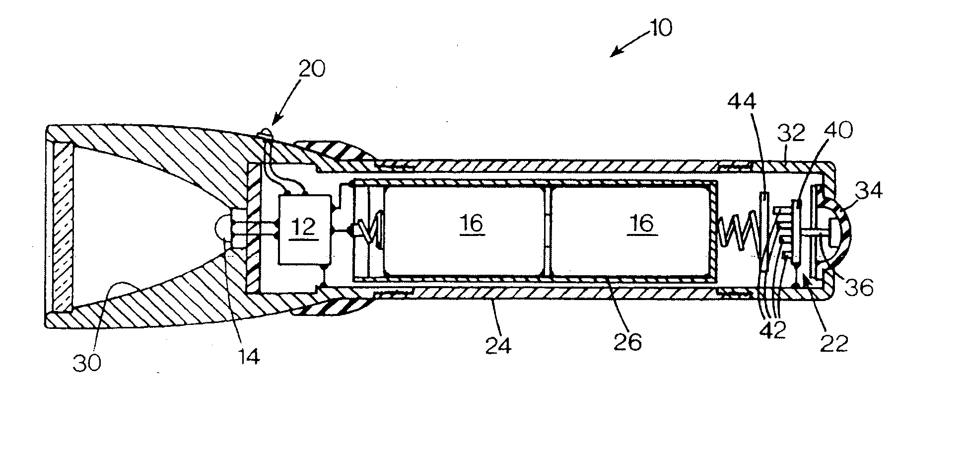
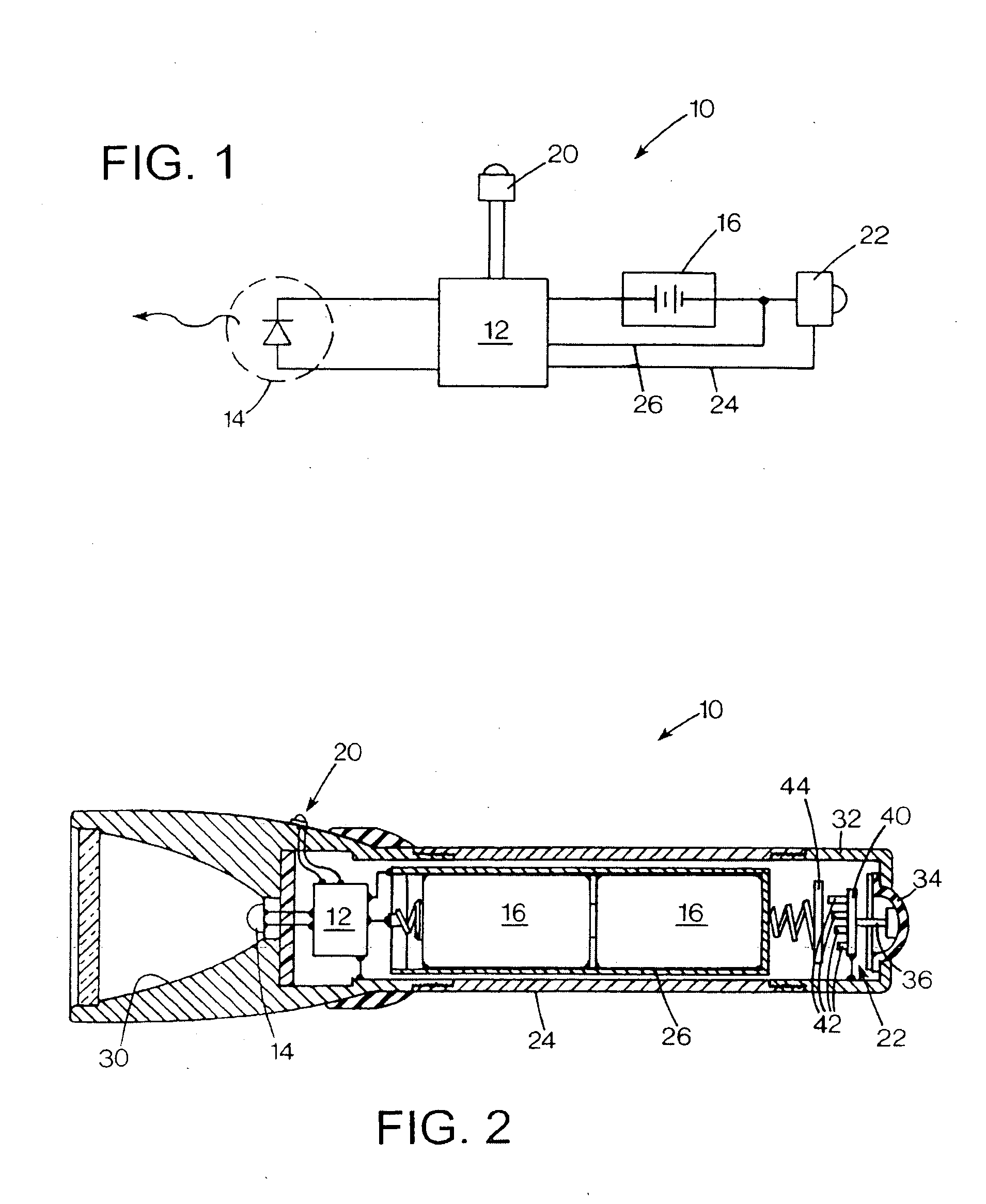
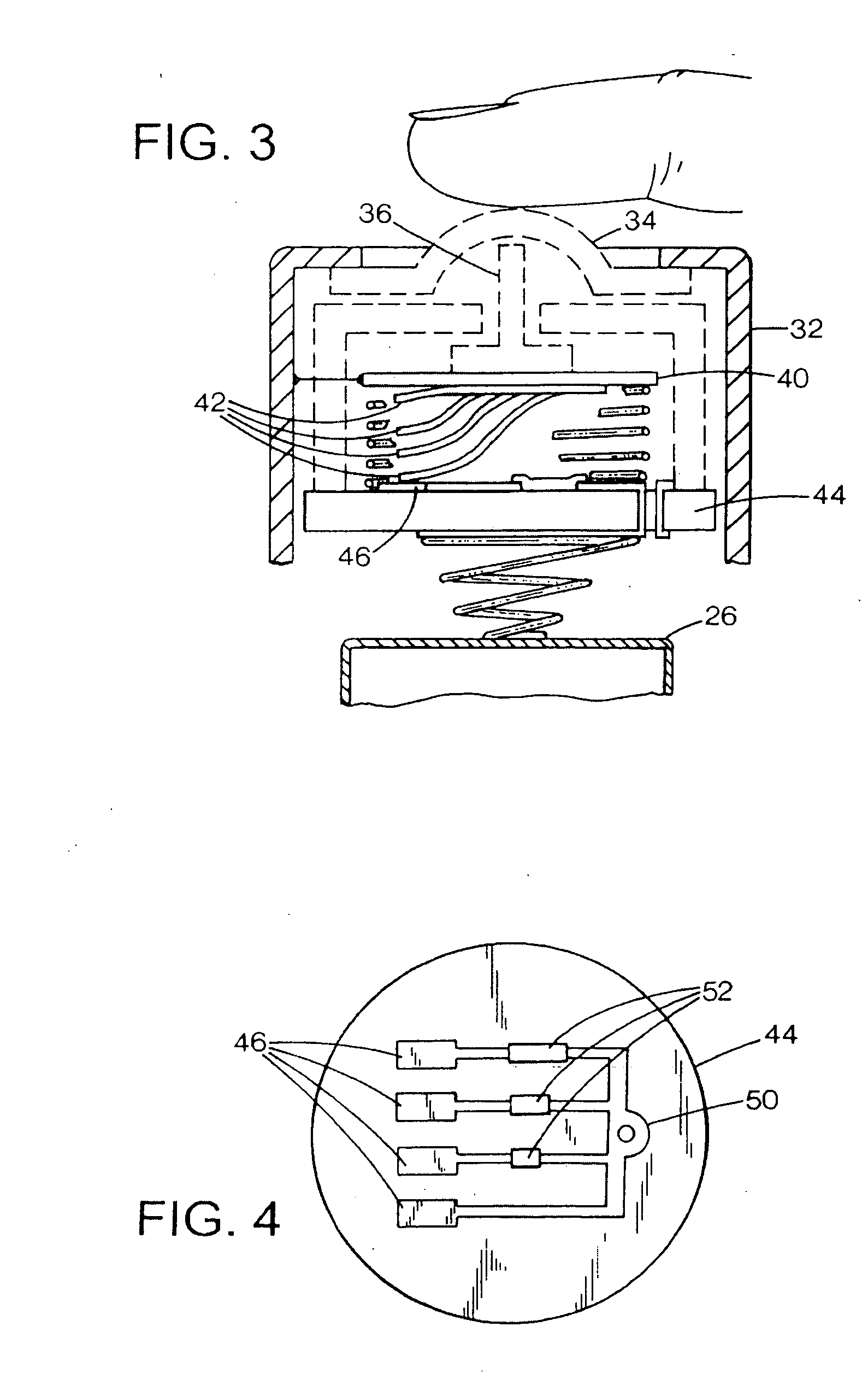
[0079]FIG. 14 shows a flashlight FIG. 6 shows a flashlight 510 that is essentially the same in many respects as that shown in FIG. 6, with an output control 520 in the form of an annular ring 522 that encircles the periphery of the flashlight's housing 524 at the forward portion that houses a lamp assembly 514. The ring is oriented in a plane perpendicular to the flashlight housing and optical axis 516, and are concentric with the cylindrical housing portion. As illustrated schematically in FIG. 6, the ring includes an embedded magnet facing toward the center of the ring, and the flashlight includes a plurality of Hall effect magnetic field sensors that operate to detect whether or not the magnet is adjacently positioned. The sensors are connected to the control circuit 512, which receives a signal to determine the angular position of the ring at any time. The sensors may be configured as discussed and illustrated above with respect to FIGS. 6 and 7. With th...


PUM


Abstract

A flashlight has a lamp assembly with a number of different output states. The flashlight has an elongated housing defining a housing axis, and a control ring encompasses the housing and rotates on the housing axis. The control ring operates to change the output state in response to rotation of the element. A detent mechanism operably connects the control ring to the housing. The detent mechanism provides a number of different stable positions of the control ring with respect to the housing, and may provide a low profile by employing a thin sheet or wire spring compressing in an axial direction.

Description

REFERENCE TO RELATED APPLICATION [0001] This is a Continuation-In-Part of U.S. patent application Ser. No. 10 / 955,139, filed Sep. 29, 2004 and entitled Flashlight with Adjustable Color Selector Switch, which is a Continuation-In-Part of U.S. patent application Ser. No. 10 / 777,597, filed Feb. 11, 2004 and entitled Flashlight with Incrementing Brightness Selector Switch, which is a Continuation-In-Part of U.S. patent application Ser. No. 10 / 732,883, filed Dec. 9, 2003, entitled Flashlight with Selectable Output Level Switching.FIELD OF THE INVENTION [0002] This invention relates to flashlights, and more particularly to switches for controlling flashlight output. BACKGROUND OF THE INVENTION [0003] Flashlights are conveniently sized battery powered portable light sources, which provide the user with a source of illumination. Said illumination could be white light or light of a specific color, or even light outside the visible range of wavelengths, such as ultra violet or infrared radiat...

Claims


Application Information

Patent Timeline
IPC IPC(8): F21L4/00F21L4/02F21V23/04
CPCF21L4/022F21L4/027F21V5/006F21V5/008F21V23/0414F21V23/0421H05B37/02F21Y2113/005F21Y2113/007H05B33/0803H05B33/0806H05B33/0845H05B33/0848F21Y2101/02Y10S362/802F21Y2115/10F21Y2113/13F21Y2113/17H05B45/14H05B45/10H05B47/10H05B45/20
Inventor KIM, PAUL Y.
Owner SUREFIRE LLC
Why Eureka
Try Eureka