Cancellation system for frequency reuse in microwave communications

a frequency reuse and cancellation system technology, applied in the field of isolation systems, can solve the problems of limited data transmission capacity, limited access to wireless services, co-channel interference, etc., and achieve the effect of better than fifty percent transmit efficiency to the antenna

Inactive Publication Date: 2005-10-27
HANGER SOLUTIONS LLC
View PDF5 Cites 55 Cited by
  • Summary
  • Abstract
  • Description
  • Claims
  • Application Information

AI Technical Summary

Benefits of technology

[0008] Another object of the present invention is to provide an interferometric beam-shaping means whereby multiple antenna beam patterns are combined to provide cancellation in predetermined directions without reducing the magnitude of the main beam. A beam-shaping circuit provides frequency-dependent weights to the electrical signals that create the beam pattern. This is done to preserve the shape of the beam pattern for broad-frequency band transmission and reception, and is applied to each component beam pattern of the interferometric beam pattern.
[0013] It is another object of the present invention to cancel transmit leakage signals resulting from impedance-differences between the antenna and the compensating dummy circuit without canceling the receive signal.
[0014] It is still another object of the present invention to cancel harmonic and intermodulation distortion signals resulting from the non-linear response of ferrite materials to the transmit signal, thereby providing the antenna system with broad-band capabilities.
[0015] It is a final object of the present invention to provide a dummy circuit in a transmit signal cancellation network for canceling direct leakage from the transmitter that provides better than fifty percent transmit efficiency to the antenna.

Problems solved by technology

Effects of these problems include limited data transmission capacity, co-channel interference, and limited access to wireless services resulting from increased demand for those services.

Method used


Image

  • Cancellation system for frequency reuse in microwave communications
  • Cancellation system for frequency reuse in microwave communications
  • Cancellation system for frequency reuse in microwave communications

Examples


Embodiment Construction

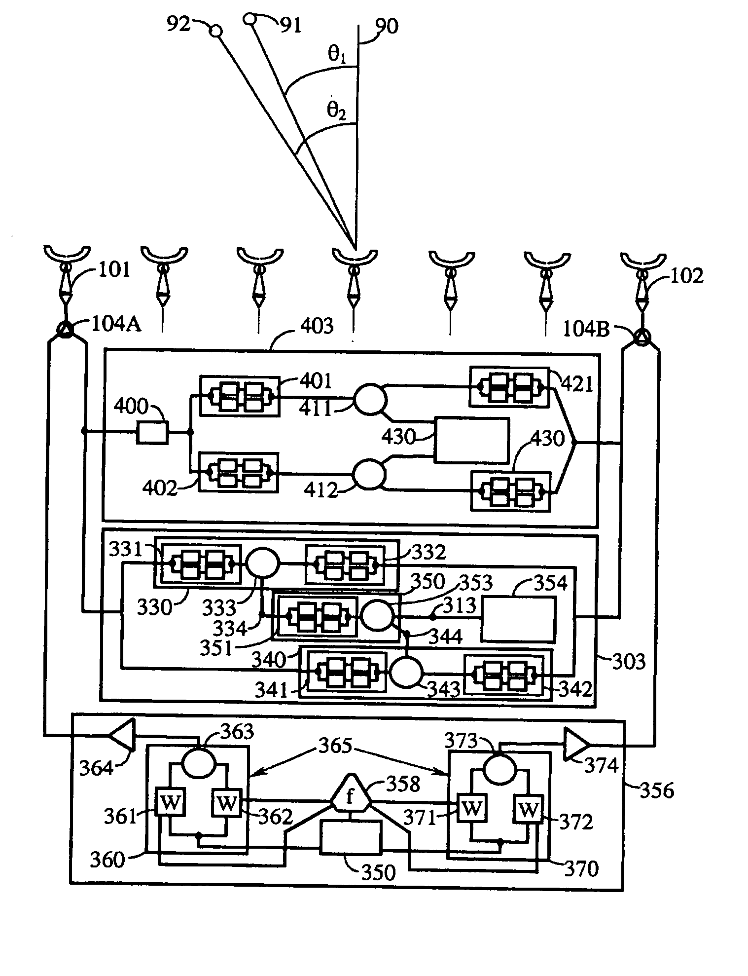
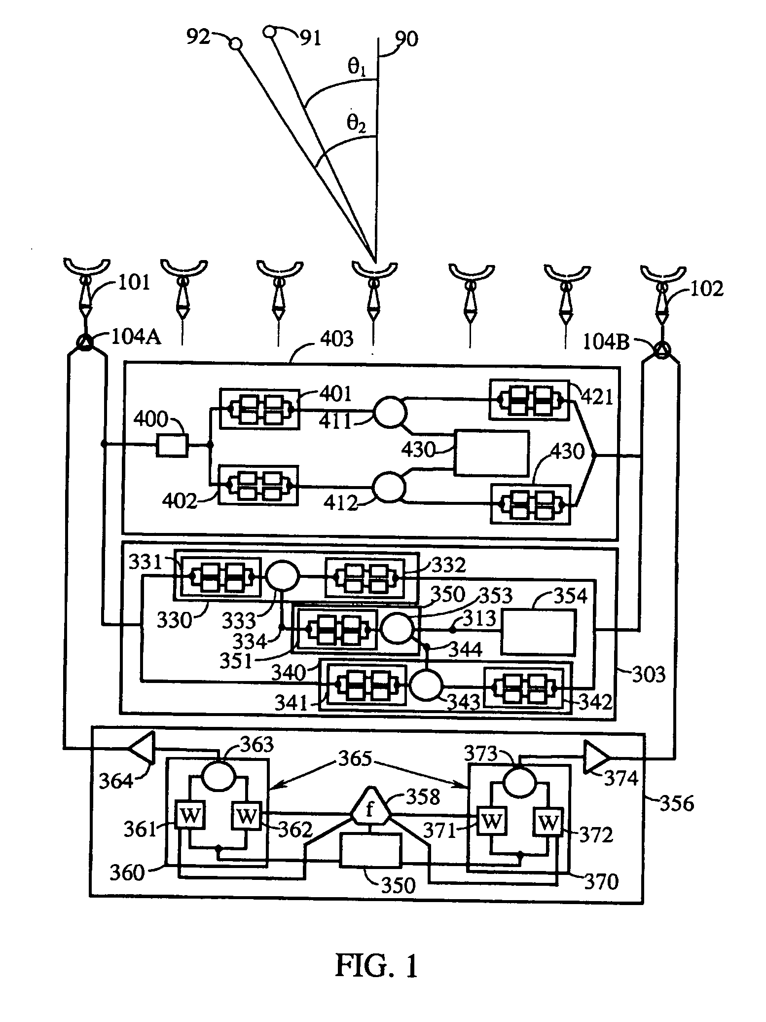
[0029]FIG. 1 shows part of an antenna array 100 of the present invention comprising a first antenna 101 and a second antenna 102 coupled to an interferometric beam-narrowing processor 303. The first antenna 101 is coupled to the processor 303 by a first three-port device 104A, and the second antenna 102 is coupled to the processor 303 by a second three-port device 104B. The processor 303 has a receiver output 313. Although only two elements 101 and 102 are shown in this array 100, the principles regarding the operation of this antenna array 100 may be extended to more than two antennas.

[0030] A first distant radio-frequency source 91 is spatially separated from a second distant radio-frequency source 92. In this case, both sources 91 and 92 radiate at a common wavelength λ; however, these sources may radiate at different wavelengths. Radiation from the first source 91 is shown as a plane wave 119 representing a common phase-front incident at the antennas 101 and 102 at a first inci...


PUM


Abstract

Substantial improvements in frequency reuse in microwave communications systems is achieved by canceling co-channel interference and transmitter leakage. Interferometric beam-narrowing reduces beamwidth without reducing peak magnitude of the beam pattern. Frequency-dependent beam-shaping compensates for frequency-dependent distortions of the beam pattern thereby improving bandwidth. A spatial demultiplexing technique utilizes spatial gain distributions of received signals to separate signals, even from co-located transmit sources, and uses microwave lensing to enhance received spatial gain distributions. Predetermined cross-polarization interference is used to separate differently-polarized receive signals. A reference branch provides a cancellation signal to a receiver to cancel transmitter leakage signals. An error signal controls an impedance-compensation circuit that is responsive to changes in antenna impedance but not to receive signals. A dc bias magnetic field applied to a magnetic permeable material adjusts non-linear distortion in a cancellation circuit for canceling distortion in a transmitter leakage signal. Discreet impedance elements approximate a circuit having distributed impedance.

Description

RELATED APPLICATIONS [0001] This is a Divisional of U.S. patent application Ser. No. 09 / 472,300, filed Dec. 27, 1999, which is a Divisional of U.S. application Ser. No. 08 / 862,859, filed May 23, 1997, now U.S. Pat. No. 6,008,760.BACKGROUND OF THE INVENTION [0002] The present invention relates generally to free-space radio frequency (RF) communication systems and, more particularly, to isolation systems that separate the receive signal from interfering signals in a RF communications system. Interfering signals include signals received by the communications antenna causing co-channel interference and transmit signal leakage of the antenna's transmitter signal into the receiver. Many electronic systems, such as radar and wireless communication systems, operate over a wide range of microwave frequencies. For example, many radar and communication systems operate in what is known as a frequency-hopping or a frequency-agile manner over very wide microwave bandwidths. The bandwidth can vary...

Claims


Application Information

Patent Timeline
Patent Type & Authority Applications(United States)
IPC IPC(8): G01S3/04G01S3/28H04B1/52H04B7/06H04B7/08H04B15/00
CPCG01S3/04H01Q3/26H04B7/086H04B1/525H04B7/0613H01Q21/06
Inventor SHATTIL, STEVE J.
Owner HANGER SOLUTIONS LLC
Why Eureka
Try Eureka