Traction cutting balloon

a technology of traction cutting and balloons, which is applied in the field of angioplasty and angioplasty balloon catheters, can solve the problems of major problems such as blockage or narrowing of blood vessels, lack of oxygenation of the heart, and obstruction of the heart and vascular disease, and achieve the effect of improving traction

Inactive Publication Date: 2005-10-27
BOSTON SCI SCIMED INC
View PDF28 Cites 50 Cited by
  • Summary
  • Abstract
  • Description
  • Claims
  • Application Information

AI Technical Summary

Benefits of technology

[0005] The present invention relates to angioplasty balloon catheters. In at least some embodiments, an example balloon catheter includes a catheter shaft having a balloon coupled thereto. A cutting member or blade is coupled to the balloon. The cutting member may include one or more traction members or a traction region that can, for example, improve traction between the balloon (or the cutting member) and a target site. These and other features are described in more detail below.

Problems solved by technology

Heart and vascular disease are major problems in the United States and throughout the world.
Conditions such as atherosclerosis result in blood vessels becoming blocked or narrowed.
This blockage can result in lack of oxygenation of the heart, which has significant consequences since the heart muscle must be well oxygenated in order to maintain its blood pumping action.
One of the major obstacles in treating coronary artery disease and / or treating blocked blood vessels is re-stenosis.
It is believed typical angioplasty balloons, alone, may not be able to expand certain of these hardened lesions.

Method used


Image

  • Traction cutting balloon
  • Traction cutting balloon
  • Traction cutting balloon

Examples


Embodiment Construction

[0014] The following description should be read with reference to the drawings wherein like reference numerals indicate like elements throughout the several views. The detailed description and drawings illustrate example embodiments of the claimed invention.

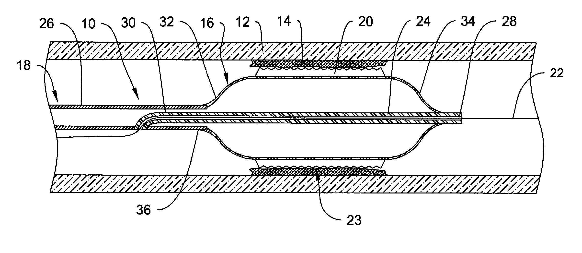
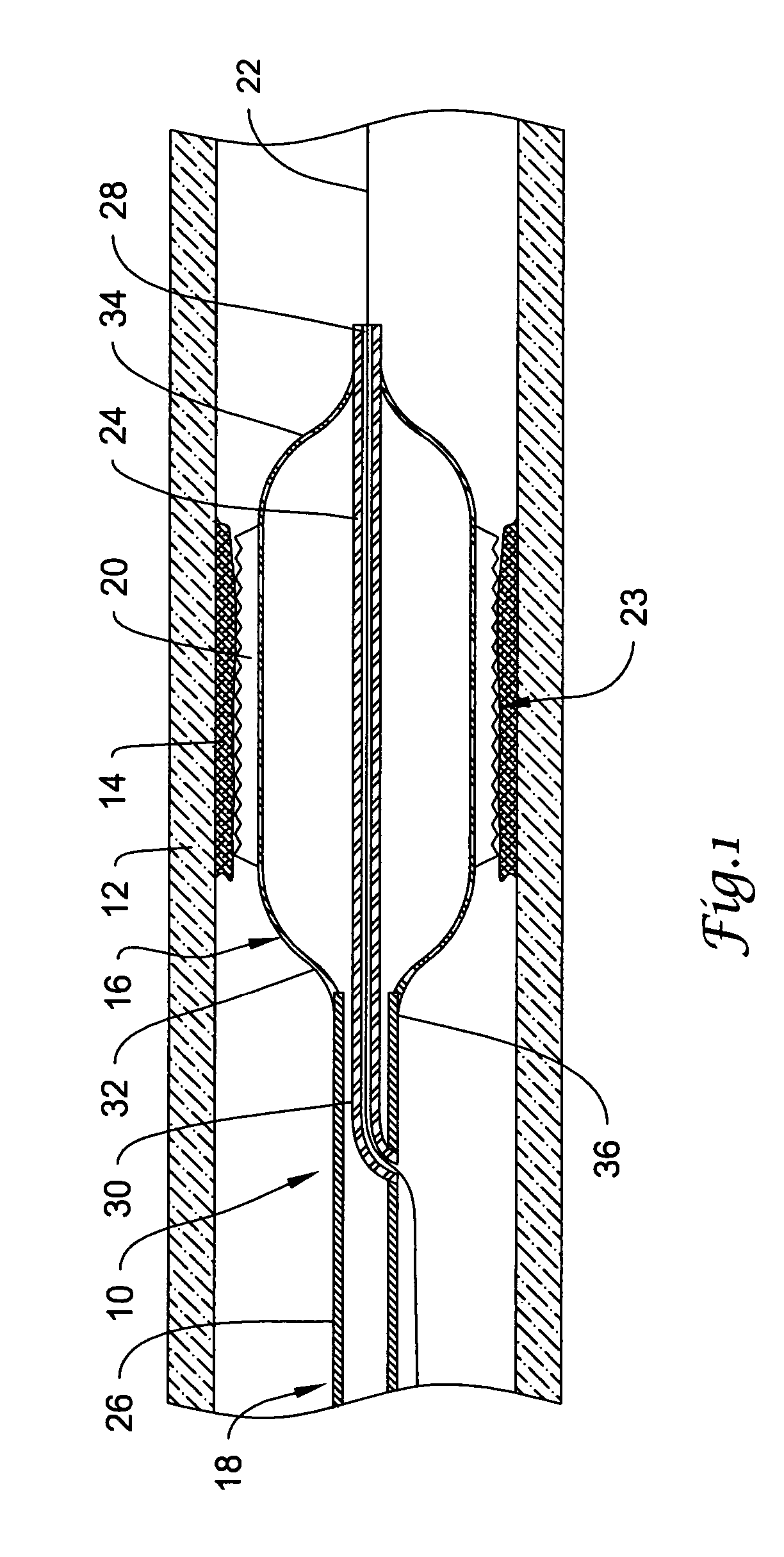
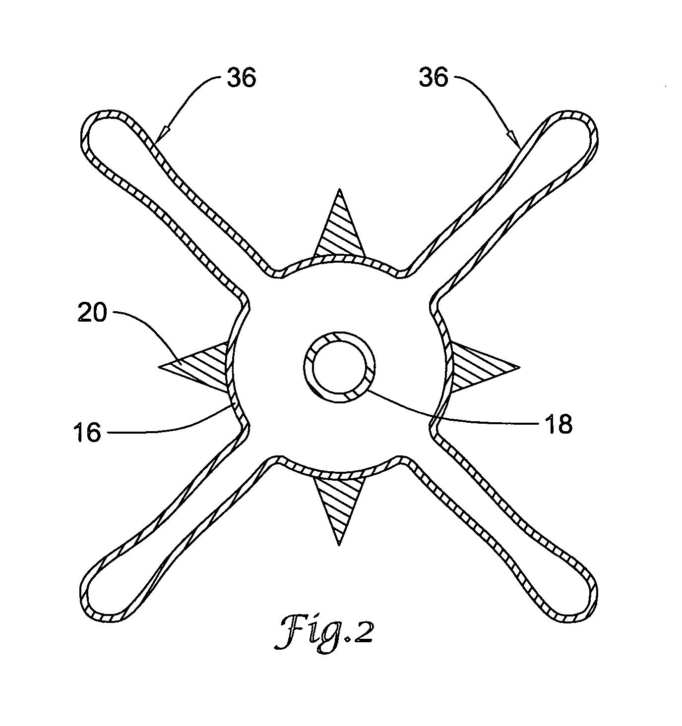
[0015]FIG. 1 is a partial cross-sectional side view of an example catheter 10 disposed in a blood vessel 12 and positioned adjacent an intravascular lesion 14. Catheter 10 may include a balloon 16 coupled to a catheter shaft 18. In a preferred embodiment, one or more cutting members or blades 20 are coupled to balloon 16. In general, catheter 10 may be advanced over a guidewire 22 through the vasculature to a target area. Balloon 16 can then be inflated to expand lesion 14, and cutting members 20 may cut lesion 14. The target area may be within any suitable peripheral or cardiac location.

[0016] Cutting members 20 may help to concentrate force exerted by catheter 10 onto lesion 14 and may cut into or otherwise sever or break up ...


PUM


Abstract

A cutting balloon catheter and methods of making and using the same. The balloon catheter may include a catheter shaft having a balloon coupled thereto. A cutting member or blade may be coupled to the balloon. The cutting member may include one or more traction members or a traction region that can, for example, improve traction between the balloon and a target site.

Description

FIELD OF THE INVENTION [0001] The present invention pertains to angioplasty and angioplasty balloon catheters. More particularly, the present invention pertains to angioplasty balloon catheters that include one or more cutting edges coupled to the angioplasty balloon. BACKGROUND OF THE INVENTION [0002] Heart and vascular disease are major problems in the United States and throughout the world. Conditions such as atherosclerosis result in blood vessels becoming blocked or narrowed. This blockage can result in lack of oxygenation of the heart, which has significant consequences since the heart muscle must be well oxygenated in order to maintain its blood pumping action. [0003] Occluded, stenotic, or narrowed blood vessels may be treated with a number of relatively non-invasive medical procedures including percutaneous transluminal angioplasty (PTA), percutaneous transluminal coronary angioplasty (PTCA), and atherectomy. Angioplasty techniques typically involve the use of a balloon cat...

Claims


Application Information

Patent Timeline
Patent Type & Authority Applications(United States)
IPC IPC(8): A61B17/00A61B17/22A61M29/02
CPCA61B17/22A61B17/320725A61B2017/22061A61B2017/00778A61B2017/00557
Inventor CHEVES, KAREN M.CROW, LOREN M.KELLEY, GREGORY S.MCAULEY, STEVEN A.RADISCH, HERBERT R. JR.ROMAN, RICARDO DAVIDWU, SHOW-MEAN
Owner BOSTON SCI SCIMED INC
Why Eureka
Try Eureka