
Detachable mount for a telescopic firearm sight

a telescopic and firearm sight technology, applied in the field of telescopic sight mounts, can solve the problems of difficult and time-consuming to attach and/or remove the scope from the base, significant loss of accuracy for long-range shooting, and disadvantages of the foregoing system, so as to achieve quick and easy mounting, flexible and customizable, and easy removal

Inactive Publication Date: 2005-11-03
SWAN RICHARD E
View PDF26 Cites 36 Cited by
  • Summary
  • Abstract
  • Description
  • Claims
  • Application Information

AI Technical Summary

Benefits of technology

[0012] In this regard, the present invention provides for a positively aligning, quick mount assembly for interfacing an auxiliary sighting device such as an optical scope with a firearm. The mounting assembly is designed to be used with a variety of sighting scopes such as are used on prior art firearms including, shotguns, rifles, black-powder weapons, combat weaponry and handguns. The new and novel positive-aligning quick mount is further designed to allow quick and easy mounting, removal and re-mounting of auxiliary sights on any firearm while eliminating the need to re-adjust or zero the scope when it is replaced in its mounted position on the firearm. The present invention is particularly suited for use in the modern type sporting and / or combat rifle that includes some form of receiver rail mounting system formed on its upper receiver, in that the present invention is modularized in a manner that makes it particularly flexible and customizable for a variety of applications.
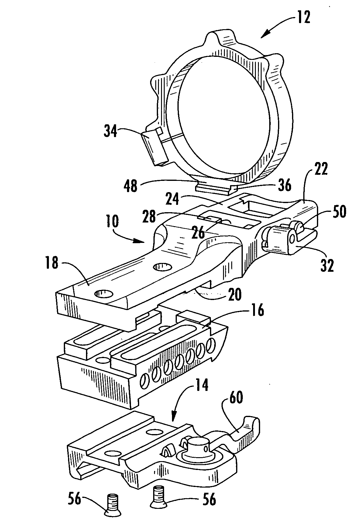
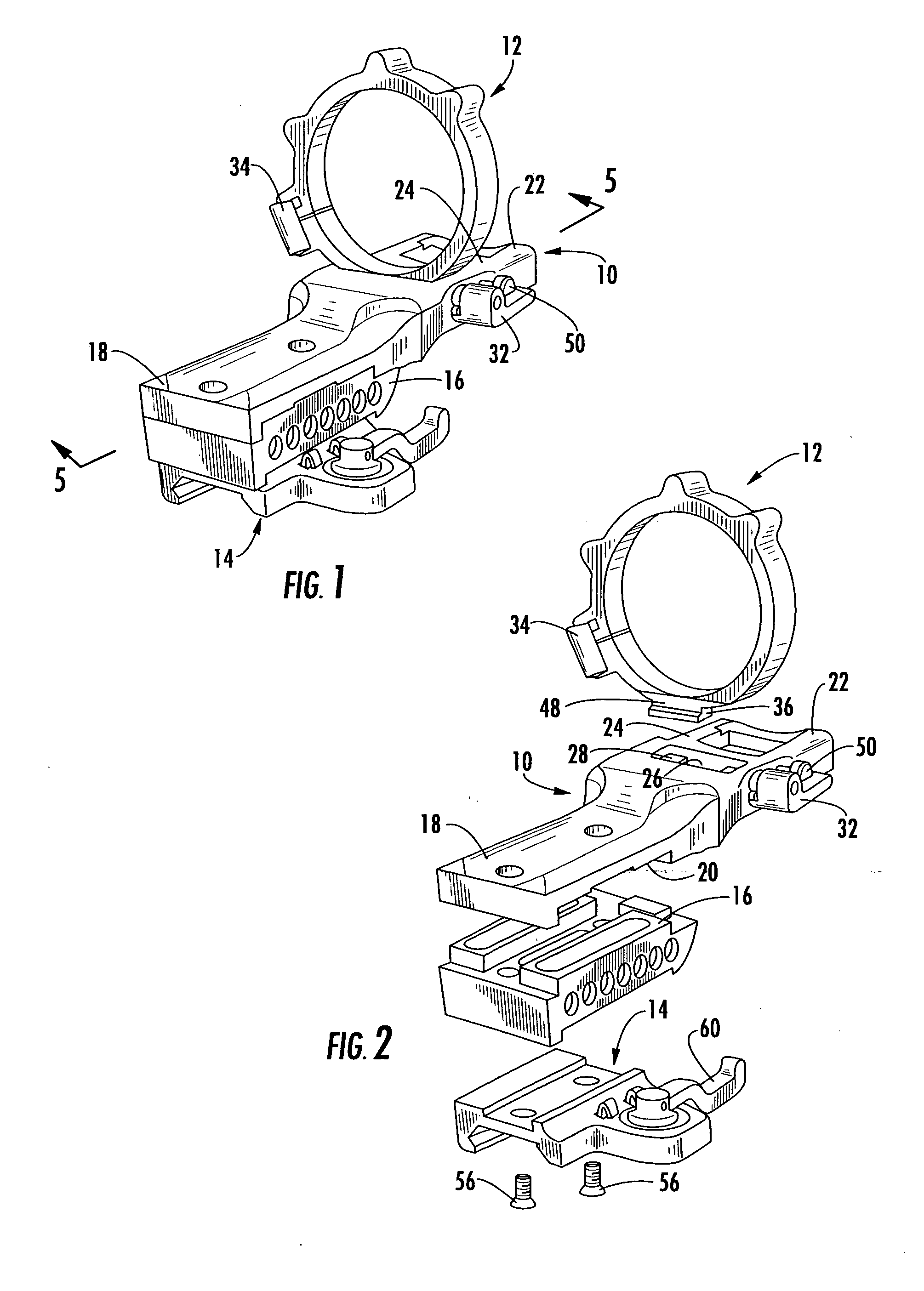
[0014] In particular the present invention provides a modular signt mounting system that allows easy removal and remounting of various sighting devices without the need for realigning the sight. The modular system includes three main components, the firearm interface, the sight receiver and the mounting ring. The firearm interface is configured to be mounted onto the firearm. In the preferred embodiment the firearm interface is mounted to a mounting rail that is either connected directly to the receiver of the firearm or is a component part to a receiver / barrel guard sleeve system. The firearm interface may include a gripping clamp that engages the sides of the rail to firmly hold the firearm interface to the fire arm. The firearm interface can be positioned in any location along the receiver and / or barrel of the firearm thereby providing for a large degree of longitudinal adjustment and positioning of the scope. The clamping mechanism in the firearm interface is operated by a single thumb lever and a cam lock assembly making removal and / or adjustment easy.
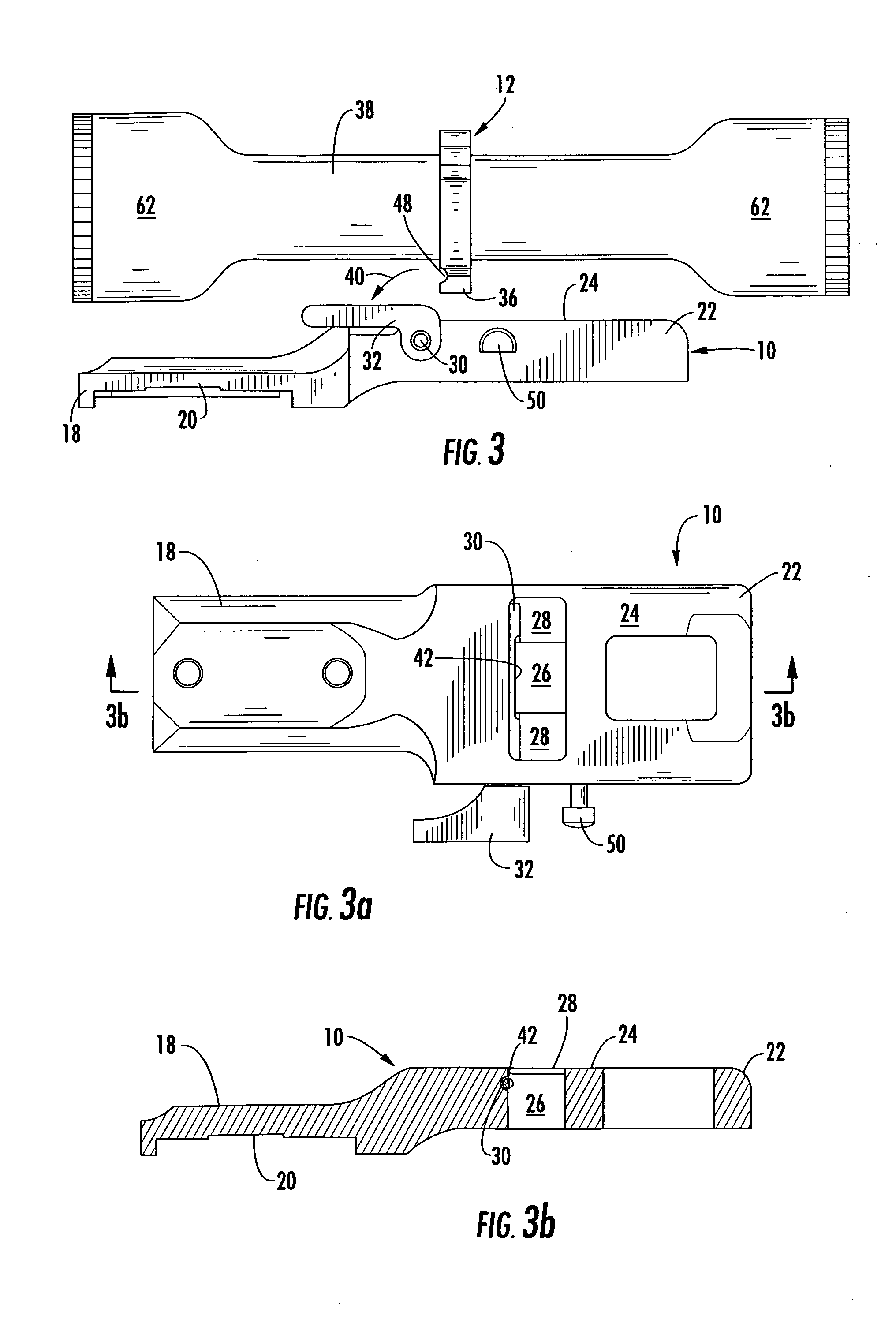
[0015] The sight receiver is an arm that is rigidly mounted onto the firearm interface using fasteners such as screws. The sight receiver serves as the interface between the firearm interface and the scope mounting ring. The sight receiver includes a mechanism that is operable to selectively retain or release the scope mounting ring thereby allowing the scope to be selectively removed from the fire arm. When mounted to the firearm interface spacers may be installed between the sight receiver and the firearm interface to adjust the height of the scope relative to the firearm. In this manner, the system can be configured to accommodate a variety of sight devices as well as to allow the scope to be positioned to avoid conflict with other accessories that may be mounted on the firearm.
[0017] It is therefore an object of the present invention to provide a mounting system that allows easy removal and remounting of an auxiliary sight for use in conjunction with a firearm. It is a further object of the present invention to provide a mounting system that enhances the manner in which an auxiliary sighting device is interfaced with a firearm wherein the sighting device can be removed and replaced onto the firearm without the need to realign the sighting device. It is yet a further object of the present invention to provide a mounting system that includes a modular interface on the base thereof for interfacing with the variety of standard receiver rail assemblies in the prior art while including an means wherein an auxiliary sighting device can be removed and replaced onto the firearm without the need to realign the sighting device interface. It yet another object of the present invention to provide a modular auxiliary sight mounting system that allows a variety of different sized and shaped auxiliary sights to be quickly, reliably and easily removed and remounted onto a firearm.

Problems solved by technology

Thus, it is often difficult and time consuming to attach and / or remove the scope from the base.
All of the foregoing systems have drawbacks or disadvantages fundamental to traditional ring mount systems.
One problem is the need for rings of different heights to mount scopes with different objective lens diameters on the same firearm.
Another problem occurs during longitudinal adjustment of the scope relative to the base and the firearm.
This can result in a significant loss of accuracy for long range shooting.
Further, once the crosshairs are moved out of alignment in this fashion, it is a time consuming task to re-align the crosshairs.
Telescopic sights, in contrast, are relatively delicate optical instruments that are vulnerable to variations in atmospheric conditions and to physical shock.
A sharp blow to a telescopic sight will often shift its point of aim.
While this device is effective in allowing the sight to be removed from the firearm until needed, the Herz type of device is slow to operate.
Further, the levers do not provide much mechanical advantage and both of them must be rotated independently to the correct position.
The telescopic sight must then be lifted off the mounting base without tilting; otherwise the device tends to become stuck.
This is an undesirable drawback in combat situations where the telescopic sight must often be removed rapidly.

Method used


Image

  • Detachable mount for a telescopic firearm sight
  • Detachable mount for a telescopic firearm sight
  • Detachable mount for a telescopic firearm sight

Examples


Embodiment Construction

[0032] Now referring to the drawings, the sight mounting assembly of the present invention is shown and generally illustrated in the figures. While the assembly may include several components and auxiliary attachments to tailor the assembly for the particular application, in the simplest form, the present invention provides for a positively aligning, quick mount assembly for interfacing an auxiliary sighting device such as an optical scope with a firearm. In the preferred embodiment, the required components include at least a sight receiver 10 and a mounting ring 12. Additionally, other components that may be utilized in the assembly as required by the particular application include a firearm interface 14 that may simply be screws or a modular mounting base and one or more spacer blocks 16.

[0033] As was stated above, the auxiliary sight mounting assembly is designed to be used with a variety of sighting scopes such as the type typically used on any variety of prior art firearms inc...


PUM


Abstract

A positively aligning, quick mount assembly for interfacing an auxiliary sighting device such as an optical scope with a firearm is disclosed. The positive-aligning quick mount device includes a sight receiver that is attached to a firearm utilizing a firearm interface and includes a mounting ring that supports the sighting device and is configured to be received and retained by the sight receiver. It is further designed to allow quick and easy mounting, removal and re-mounting of auxiliary sights on any firearm while eliminating the need to re-adjust or zero the scope when it is replaced in its mounted position on the firearm.

Description

CROSS-REFERENCE TO RELATED APPLICATIONS [0001] This application is related to and claims priority from earlier filed U.S. Provisional Patent Application No. 60 / 538,954, filed Jan. 23, 2004, the contents of which are incorporated herein by reference.BACKGROUND OF THE INVENTION [0002] The present invention relates generally to a telescopic sight mount for firearms. More specifically, the present invention is related to a detachable mount for a telescopic sight that allows the user to easily interchange or remove and store the sighting device utilized on the firearm while also providing quick and positive alignment of the sighting device when repositioning the device on the firearm. [0003] In the prior art, auxiliary sighting devices are typically rigidly mounted onto the top of the firearm receiver. Generally, these prior art firearms, such as rifles, shotguns, black-powder weapons and handguns, typically include spaced apart attachment points located on the top surface of the receive...

Claims


Application Information

Patent Timeline
Patent Type & Authority Applications(United States)
IPC IPC(8): F41G1/38F41G1/387F41G11/00
CPCF41G11/003
Inventor SWAN, RICHARD E.
Owner SWAN RICHARD E
Learn More