
Educational accelerometer

an accelerometer and accelerometer technology, applied in the field of education and demonstration, can solve the problems of complex cabling and mounting problems, large industrial sensors are usually too big and expensive for use on the desktop, and achieve the effects of accurate alignment of sensitive points, easy installation and removal, and accurate alignmen

Inactive Publication Date: 2007-07-26
LALLY ROBERT WILLIAM
View PDF14 Cites 4 Cited by
  • Summary
  • Abstract
  • Description
  • Claims
  • Application Information

AI Technical Summary

Benefits of technology

[0013] For quick, easy installation and removal, the central hole in the elastic housing also snuggly fits and grips an oversize mating post protruding from the test subject. Residual stresses in the elastic housing firmly press and hold the mating interface surfaces together in intimate contact, ensuring faithful transmission of motion, and accurate alignment of the sensitive, cylindrical axis of the accelerometer normal to the mounting surface.
[0014] The popular, low-cost, electret microphone, now produced by the millions for toys and cell phones, incorporates a built-in ICP type isolation amplifier that operates over two flexible wires from a computer expanded to display electronic signals, like an oscilloscope.
[0017] Therefore the primary object of this invention is a low-cost, sensitive, rugged, light weight, flexibly cabled, easy-to-install, accelerometer for sensing the motion of educational structural models during experiments testing the behavior and monitoring the health monitoring of things.

Problems solved by technology

Industrial sensors are usually too big and expensive for use on desktop, educational, structural models.
Although some modern semiconductor strain gage and MEMS (Micro-Electro-Mechanical Systems) type sensors are now being used on educational models, they present complex cabling and mounting problems.
Modified, these modern marvels show promise for motion sensing, but present other problems.
But, finding practical ways to permanently attach the mass to the diaphragm, environmentally seal the assembly, sufficiently vent, and conveniently install has stymied development.

Method used


Image

  • Educational accelerometer
  • Educational accelerometer
  • Educational accelerometer

Examples


Embodiment Construction

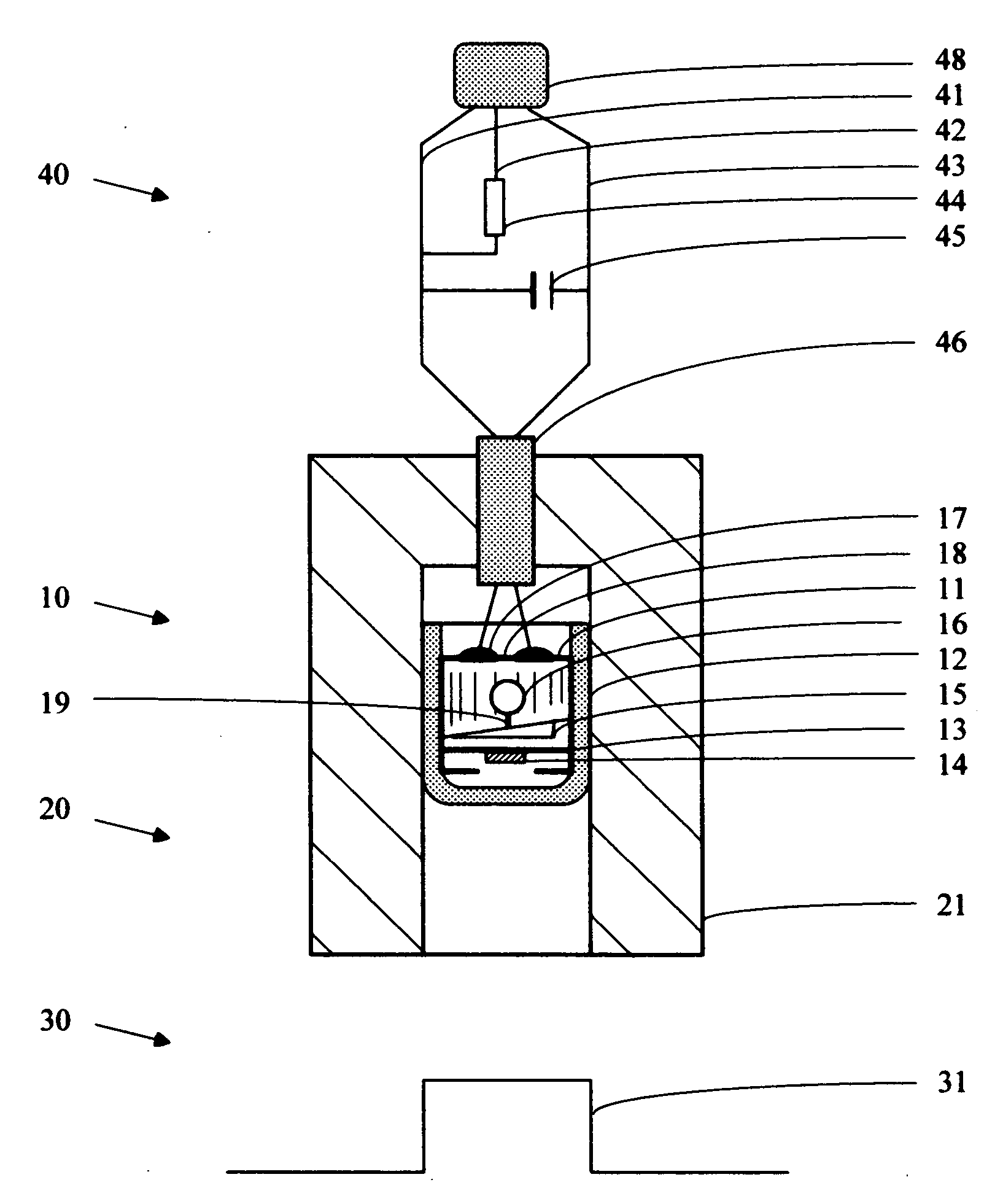
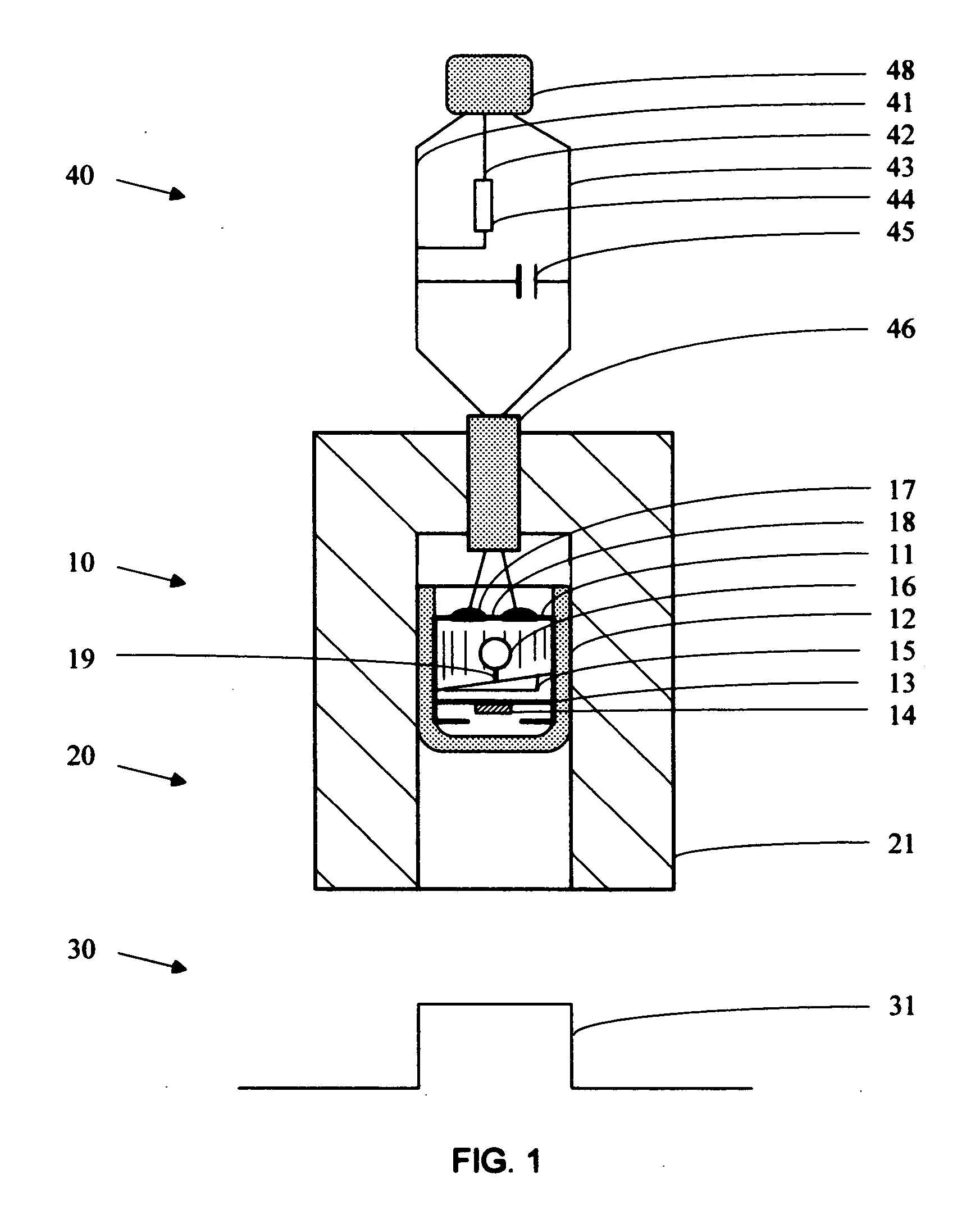
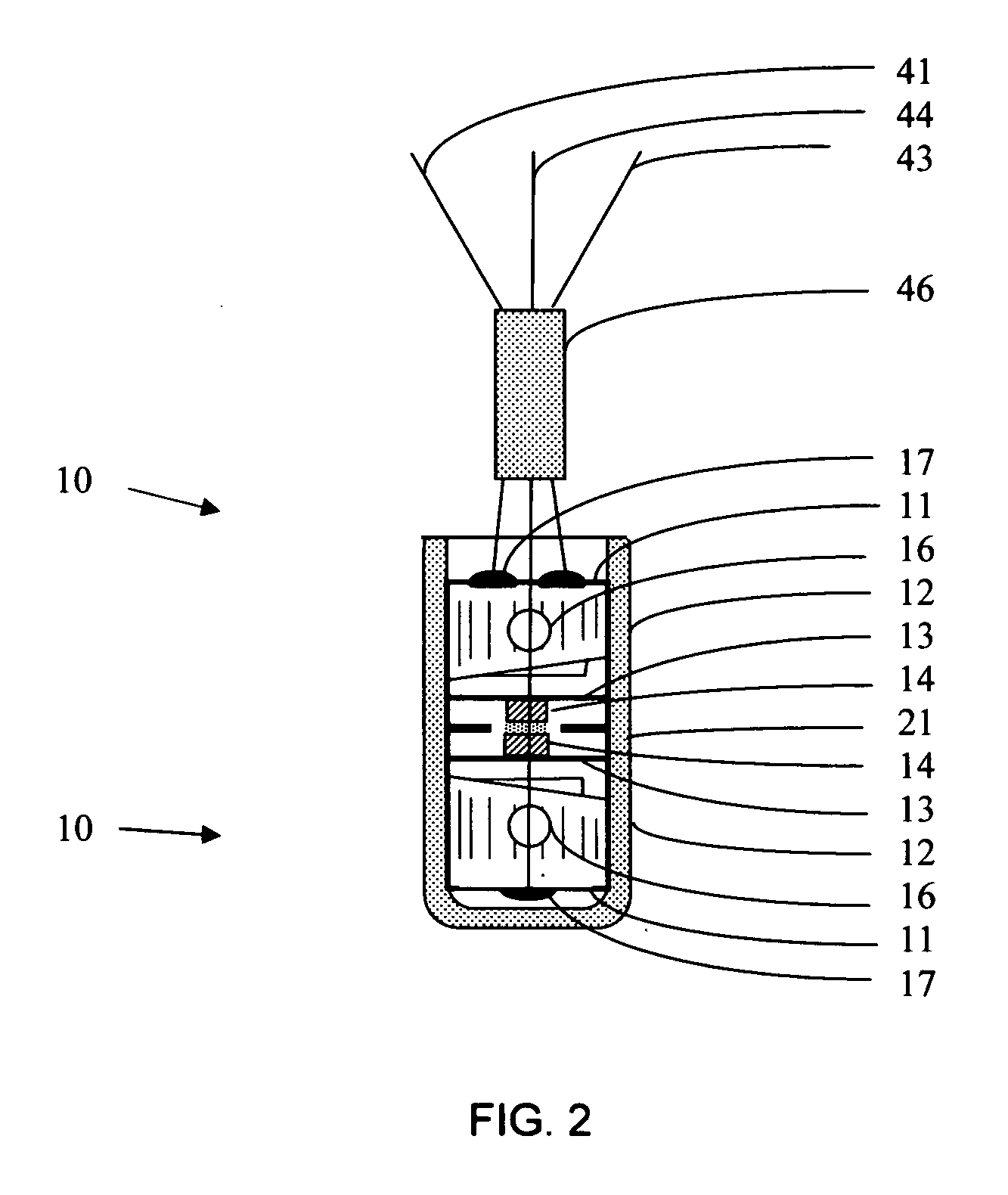
[0028]FIG. 1 illustrates an educational accelerometer containing a modified electret microphone 11 with a mass 14 adhesively attached to its diaphragm 13, sealed in a vinyl plastic cap 12, and embedded in a hard rubber housing 21 that plugs onto a post protruding from a test object 31. Snug fits, residual stresses, and friction at mating interface surfaces clamp and hold the light weight parts together, and facilitate assembly, installation, and removal.

[0029] Through transfers of energy as force and motion, the sensor capsule 10 structurally senses motion of the test object 30. Transferring energy, when the housing 21 plugs onto a mating post 31 protruding from a test object 30, and is accelerated in a direction normal to the plane of said diaphragm 13, the force required to accelerate mass 14 to follow the motion of housing 21 deflects diaphragm 13, generating an output signal from said ICP microphone assembly 10 representing the acceleration aspect of motion being experienced.

[...


PUM


Abstract

For testing the behavior and monitoring the health of things, a novel, simple, low cost, highly sensitive, light weight, easy to install, flexibly wired, sophisticated accelerometer senses the motion of educational structural models that demonstrate eneraction—how the world and sensors work. A modified electret microphone with a mass adhesively attached to its diaphragm is embedded in a hard rubber housing, insulating it against environmental noise and temperature changes. Residual stresses in the housing, which plugs onto and grips a post protruding from the test object, ensures intimate interface surface contact and faithful transmission of motion. Containing an internal isolation amplifier, and operating over two ordinary wires, the sensor embodies popular, ICP (integrated-circuit-piezoelectric) technology. Standard telephone cable output connectors mate with educational, data-acquisition accessories for computers.

Description

CROSS REFERNECE TO RELATED APPLICATION [0001] Not applicable STATMENT REGARDING FEDERALLY SPONSERED RESEARCH OR DEVELOPMENT [0002] Not applicable BACKGROUND OF THE INVENTION [0003] The present invention generally relates to education and demonstration, and to measuring and testing. More specifically it relates to a sophisticated, low-cost, integrated-circuit-electrostatic (ICE), plug-on sensor for electronically sensing motion involved in the behavior testing and health monitoring of educational structural models sensibly demonstrating eneraction—what makes the world and sensors work. [0004] Various types of physical models have been employed for ages to help teach science and technology, and to explore reality. Applying modem technology, many such educational models now employ computers displaying signals from electronic sensors to facilitate learning and teaching. Among the multitude of structural models and sensors available today, obvious wants and needs still exist for new and ...

Claims


Application Information

Patent Timeline
Patent Type & Authority Applications(United States)
IPC IPC(8): G01P15/00
CPCG01P15/09G09B23/08G01P15/125
Inventor LALLY, ROBERT WILLIAM
Owner LALLY ROBERT WILLIAM
Learn More