
Apparatus and method for measuring characteristics of fluid spray patterns

Active Publication Date: 2005-11-03
SPRAYING SYST
View PDF5 Cites 27 Cited by
  • Summary
  • Abstract
  • Description
  • Claims
  • Application Information

AI Technical Summary

Benefits of technology

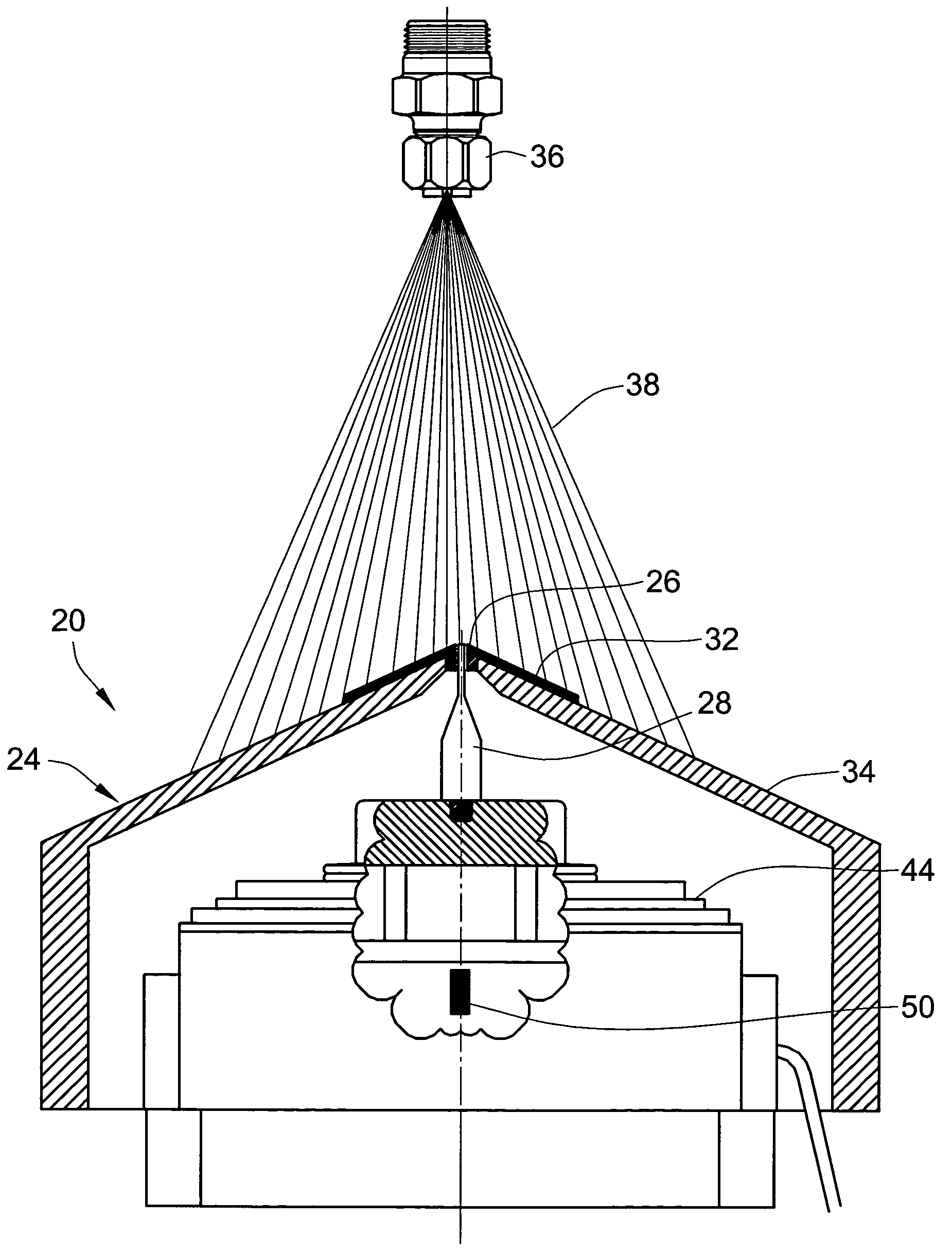
[0007] In accordance with a feature of the invention, the sensing pin and the aperture in the protection plate have a special geometry that enables the pin to reliably sense the impact of high-pressure spray of a fluid, such as water or air, without producing erroneous data or a high level of noise that buries the real readings of the pressure impacting on the load cell. In one implementation, the aperture diameter is preferably about 0.075″ larger than the diameter of the sensing end of the pin. Alternatively, the height of the pin and the dimensions of the pin and the aperture are such that the pin is allowed to have up to one degree of tilting when the sensing end of the pin moves about within the aperture under the impact of the high pressure fluid.

Problems solved by technology

The high pressure of the spray from a high-impact nozzle, however, can make it very difficult to obtain reliable and repeatable readings of the fluid pressure at different points in the spray pattern.

Method used


Image

  • Apparatus and method for measuring characteristics of fluid spray patterns
  • Apparatus and method for measuring characteristics of fluid spray patterns
  • Apparatus and method for measuring characteristics of fluid spray patterns

Examples


Embodiment Construction

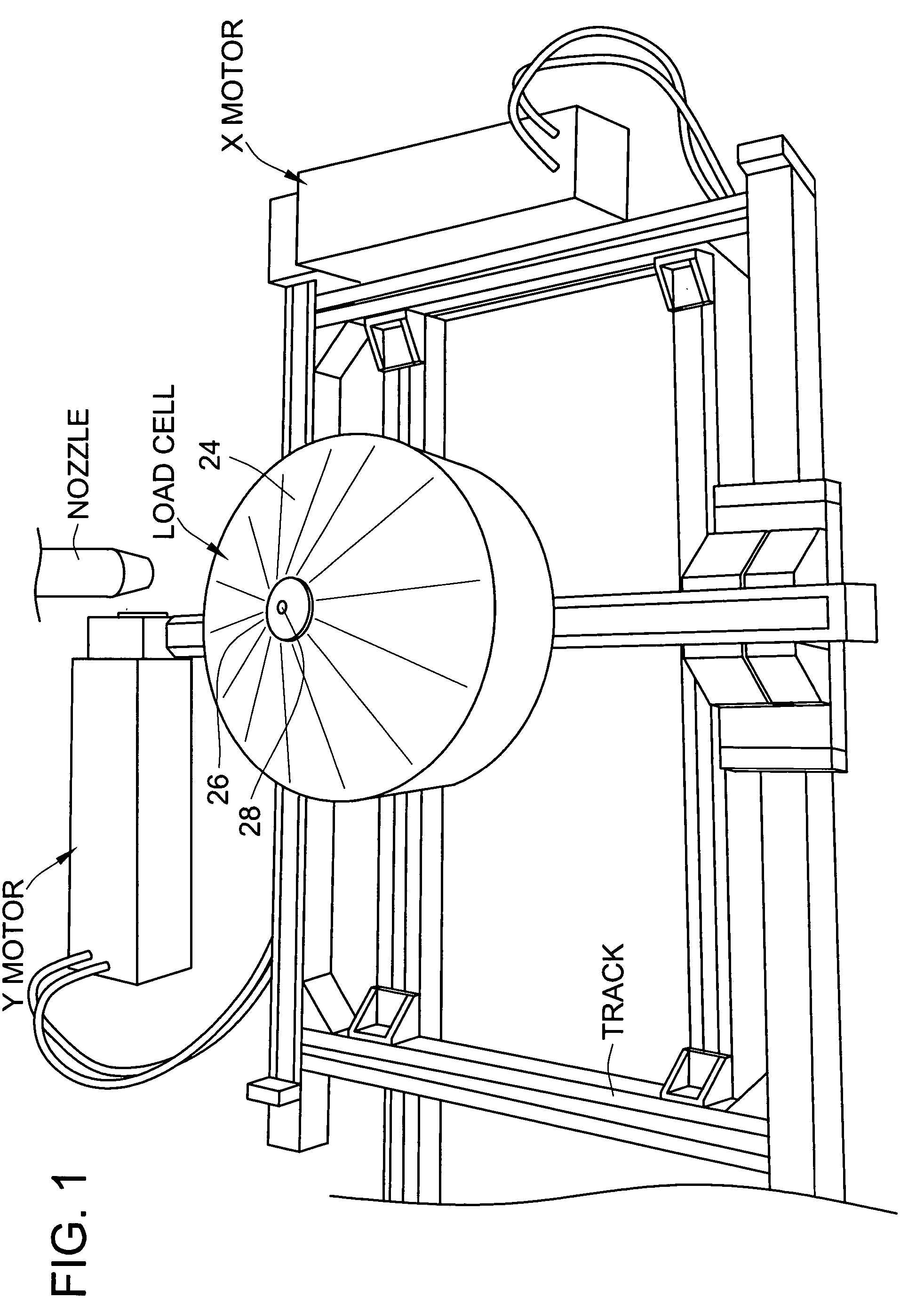
[0025] Turning now to the drawings, in which like numbers are used to refer to similar elements, FIG. 1 shows a portion of an impact testing system. As shown in FIG. 1, the impact testing system includes a load cell 20 that is mounted on a transport system 22. In the embodiment shown in FIG. 1, the load cell 20 is enclosed in a protective housing 24 that has a round drum-like shape, with a slightly conical top surface. At the center of the top surface of the protective housing is an aperture 26. Inside the aperture 26 is a sensing pin 28, which is mounted inside the housing 24.

[0026] As shown in FIG. 4, the protective housing 24 includes an impact cover plate 32 is disposed at the center of the conical top of the housing, and a protective cover 34. FIGS. 10a-c show various views, including a cross-sectional view, of the impact cover plate 32, and FIG. 11a-d show various views, including a cross-sectional view, of the protective cover 34. The impact cover plate 32 is subject to a hi...


PUM


Abstract

An automated impact testing system provides reliable measurements of spray patterns of high-impact nozzles. The impact testing system includes a load cell mounted on a transport for controlled movements in two directions. The load cell includes a sensing pin extending through an aperture in a protective housing of the load cell. A special relationship between the dimensions of the sensing pin and the aperture allows the load cell to produce error-free impact measurement data.

Description

RELATED APPLICATIONS [0001] This application claims the priority of U.S. Provisional Application 60 / 565,997, filed Apr. 28, 2004.FIELD OF THE INVENTION [0002] This invention pertains generally to spraying systems for spraying fluids such as water and air, and more particularly to an apparatus and method for measuring the spray characteristics of fluid spray patterns generated by high-impact spray devices. BACKGROUND OF THE INVENTION [0003] High-impact spray nozzles are used in various industrial and other applications where a spray of high-pressure fluid (e.g., water or air) is required. For instance, high-impact water sprays are used in steel industry to de-scale rolled steel sheets. For industrial applications, the highest impact per unit area achievable is an important performance parameter for a high impact spray nozzle. Moreover, a high-impact spray nozzle is typically designed to provide a well-defined spray pattern with substantially even pressure within the pattern. To provi...

Claims


Application Information

Patent Timeline
IPC IPC(8): B05B9/01B05B15/00G01L5/00G01N3/08G01N3/30
CPCB05B9/01G01L5/0052B05B15/00B05B12/082
Inventor TANNER, KRISTYCHINN, PATRICKROBB, LESLI
Owner SPRAYING SYST
Learn More