Targeted guided wire level measuring device

a technology of level measurement device and guided wave, which is applied in the direction of liquid/fluent solid measurement, instruments, machines/engines, etc., can solve the problems of weak return signal, inability to detect weak signals, and inability to accurately detect sonic devices

Inactive Publication Date: 2005-11-03
K TEK
View PDF13 Cites 47 Cited by
  • Summary
  • Abstract
  • Description
  • Claims
  • Application Information

AI Technical Summary

Benefits of technology

[0006] The present invention is an improvement in a guided wave device comprising a reflective target system coupled to the waveguide. The target system includes a fl

Problems solved by technology

For instance, sonic devices can be inaccurate if the propagating velocity is not compensated for temperature, pressure and humidity conditions along the propagation path of the signal.
In very deep t

Method used


Image

  • Targeted guided wire level measuring device
  • Targeted guided wire level measuring device
  • Targeted guided wire level measuring device

Examples


Embodiment Construction

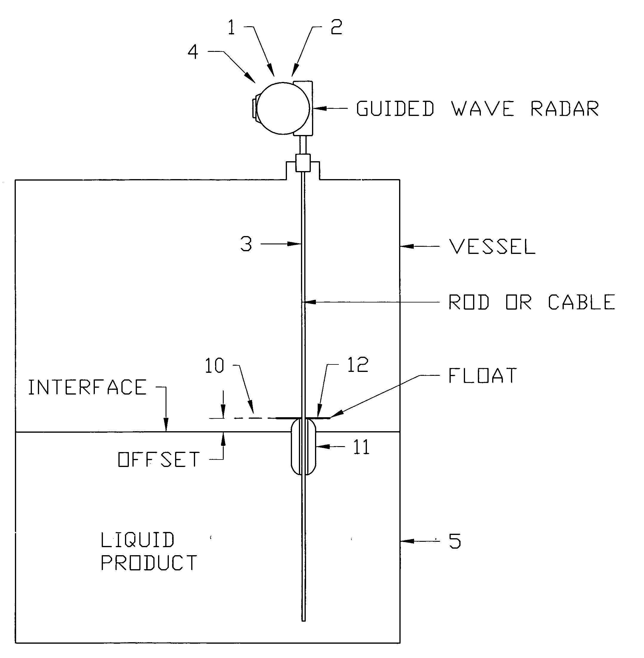
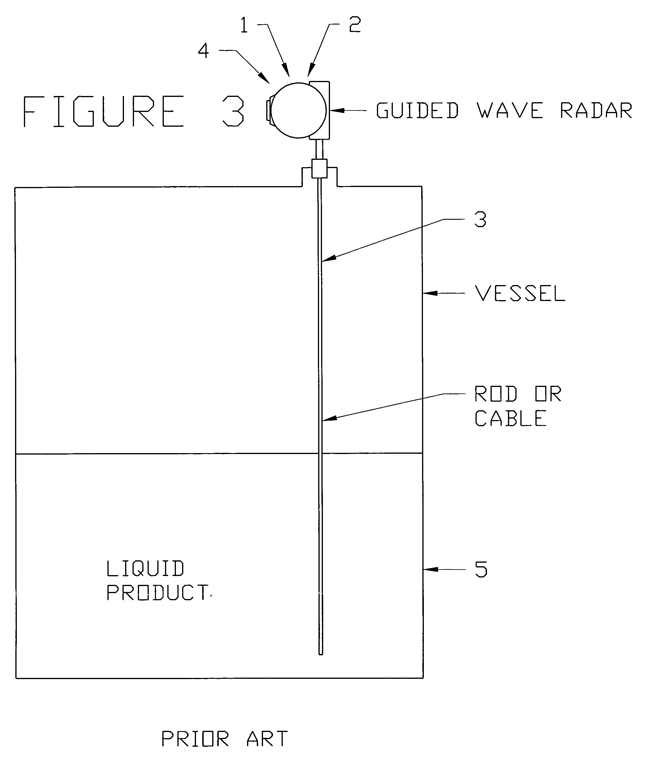
[0020] The reflective target system is designed to work with a basic guided wave device. The basic guided wave device is shown in FIG. 3 disposed in a tank 5, although this system may also be deployed in an external chamber fluidly connected to the tank (not shown). The basic guided wave device includes a signal generator / emitter 1 and a signal receiver 2 (the emitter and receiver may be integrated into a single unit as depicted in FIG. 3) and a waveguide 3 operationally connected to the emitter 1 and receiver 2. The waveguide 3 may be a cable, or solid rod or of other suitable construction known in the art of various geometries. The guided wave device will either include or work in conjunction with a processor 4 to track and compare time of emission and time of reception (or accumulated time beginning at time of emission and ending at time of signal reception). The processor 4 may be located on the device or in a remote location. As shown in FIG. 3, the processor 4 is located on th...


PUM


Abstract

The invention is an improved guided wave level measurement device. A guided wave measuring device includes a waveguide, a signal generator and a signal receiver, where the signal generator and signal receiver are operationally connected to the waveguide. The improvement included a target which is displaceable with respect to the waveguide and coupled to the waveguide. The target presents a reflective surface and the position of the target is detectable through time of flight measurements of a signal generated by the signal generator.

Description

FIELD OF THE INVENTION [0001] The present invention relates to a system and method for monitoring fluid levels in containers, such as storage tanks, and more particularly, to systems using guided wave level measurement devices. BACKGROUND OF THE INVENTION [0002] Various devices have been conventionally employed to measure the level of a fluid or the interface levels between two mediums (such as air / water or oil / water). Generally, these devices consist of a sensor within a container, and means for sending data from the sensor to a remote location where it would be detected and converted into a usable format representative of the level of fluid within the container. [0003] Mechanical and electromechanical sensors include floats and magnetostrictive devices. One means of level detection is through non-contact time of flight measurements, which generally have no sensor located at the fluid interface. In non-contact devices, a signal source or generator is used to emit a pulse of energy ...

Claims


Application Information

Patent Timeline
IPC IPC(8): G01F23/284G01F23/52G01F23/72G01F25/00
CPCG01F23/284G01F25/0061G01F23/72G01F25/20
Inventor KULL, CARL
Owner K TEK
Why Eureka
Try Eureka