Gas feeding system for an internal combustion engine, having an improved pressure reducing valve

a gas feeding system and pressure reducing valve technology, applied in the direction of valve operating means/release devices, machines/engines, functional valve types, etc., can solve the problems of increasing the risk of gas leakage towards the outside, cumbersome valves of a known type, not entirely reliable, etc., to achieve efficient and reliable operation, simple and low-cost structur

Inactive Publication Date: 2005-11-03
METATRON
View PDF6 Cites 8 Cited by
  • Summary
  • Abstract
  • Description
  • Claims
  • Application Information

AI Technical Summary

Benefits of technology

[0022] The purpose underlying the present invention is to provide a supply system of the known type described above which will enable the drawbacks referred to above to be overcome, which, more in general, will have a relatively simple and low-cost structure, which, notwithstanding this, will guarantee an operation that is efficient and reliable, and which will moreover be safer as regards the risk of leakage of gas into the external atmosphere.

Problems solved by technology

Possible deformations of the structure increase the risk of leakage of gas towards the outside.
Basically then, the valve of a known type proves cumbersome, not altogether reliable with respect to the risk of leakage of gas into the external atmosphere, and finally also has a relatively complicated and costly structure.
In addition to this, the valve described above does not enable an optimal response during the transient regimes.
There is finally the risk of a deterioration of the load of the spring over time, with consequent variation of the regulated pressure.

Method used


Image

  • Gas feeding system for an internal combustion engine, having an improved pressure reducing valve
  • Gas feeding system for an internal combustion engine, having an improved pressure reducing valve
  • Gas feeding system for an internal combustion engine, having an improved pressure reducing valve

Examples


Embodiment Construction

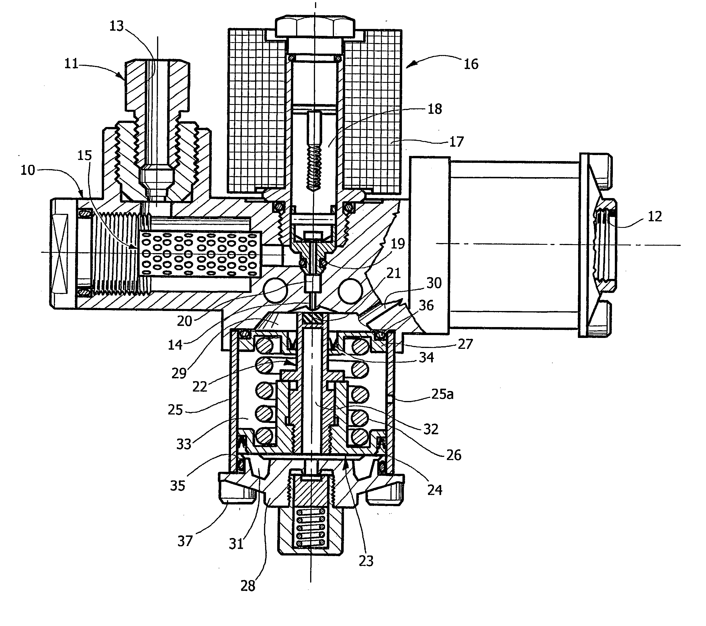
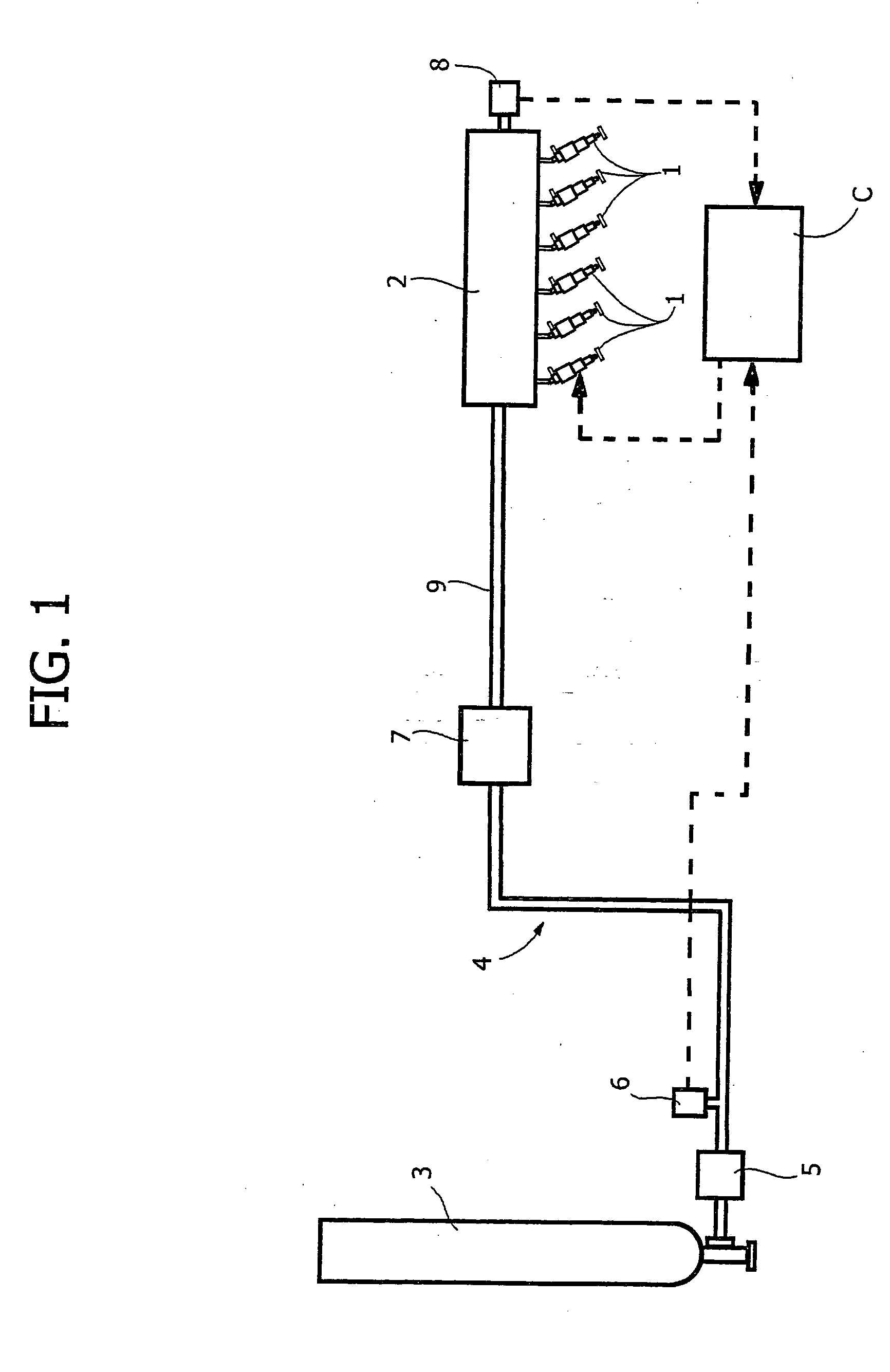
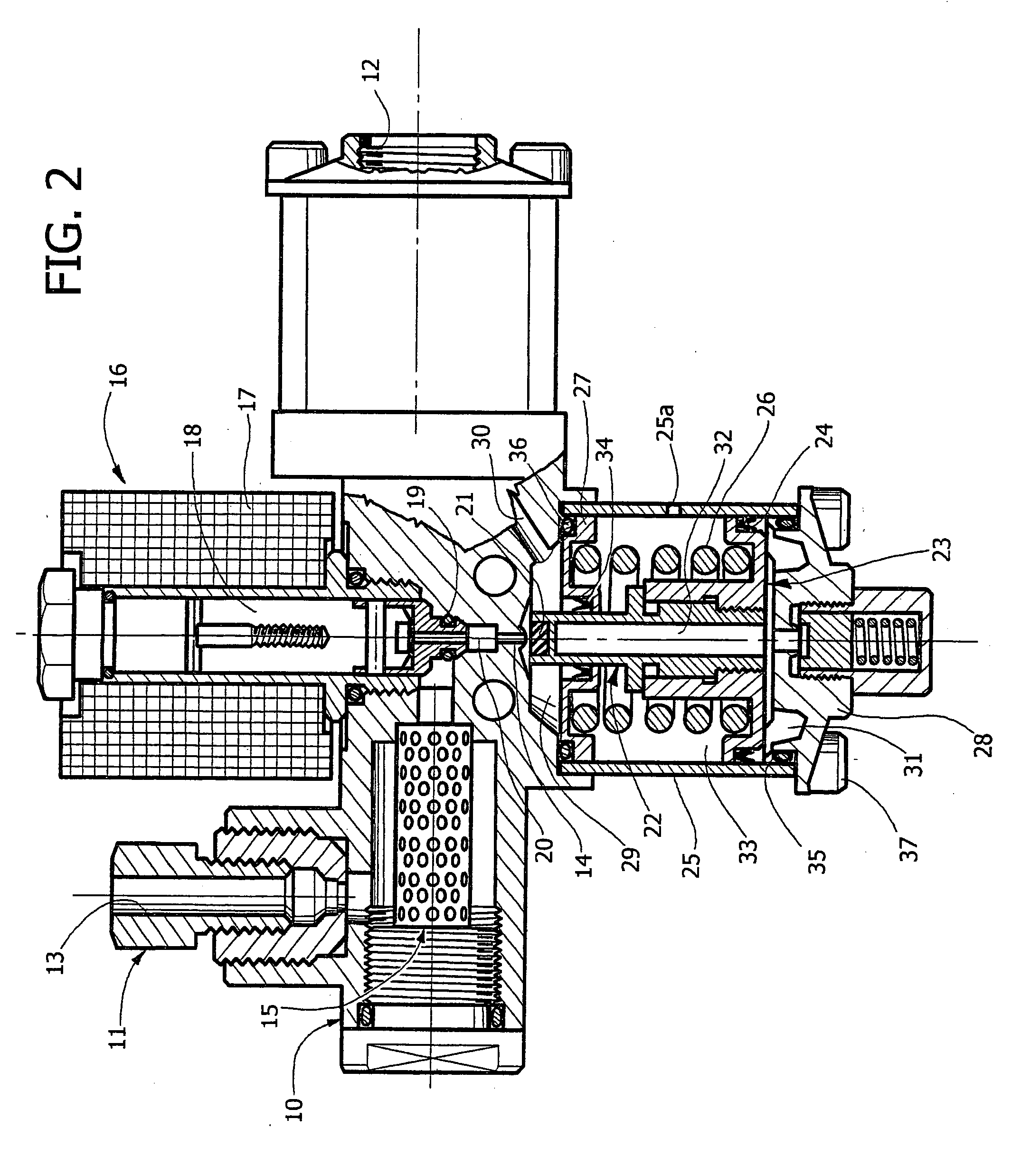
[0043] According to the invention, a supply system is proposed of the type illustrated in FIG. 1, in which, however, the pressure-reducing valve 7 is obtained in accordance with what is illustrated by way of example in FIG. 3. In said figure, the parts that correspond or have a function similar to those of FIG. 2 are designated by the same reference numbers.

[0044] Also the valve of FIG. 3 has a valve body 10 within which a restricted passage 14 is defined, set in communication between an inlet passage 13 made in an inlet connector 11 and an outlet passage 12 made in an outlet connector 12a. The connector 11 is designed to be connected to the pipe 4 (FIG. 1), which carries the gas coming from the reservoir 3. The connector 12a is designed to be connected to the pipe 9 that takes the gas at reduced pressure to the rail 2. The example illustrated in FIG. 3 relates to a single-stage valve that performs a single pressure jump. However, nothing prevents a valve being envisaged that has t...


PUM


Abstract

In a gas-supply system for internal-combustion engines, a pressure-reducing valve is set between the reservoir of the gas and a distribution manifold or rail that feeds the gas to a series of electromagnetically controlled injectors associated to the various cylinders of the engine. The pressure-reducing valve has a piston member that faces a chamber set downstream of a restricted passage defined inside the body of the valve in communication between the inlet connector and the outlet connector. The piston member is pushed by thrust means towards a position in which it causes opening of an open/close element that controls the communication between said restricted passage and the inlet connector. The piston member is preferably provided with a single seal gasket that prevents leakage of gas towards the outside through the sliding coupling of the piston member within the respective guide bushing. The thrust means to which the piston member is subject may be constituted by spring means, or else by a pilot-pressure signal, in the case where it is intended to obtain a variable reduction of the pressure according to the operating conditions of the system.

Description

BACKGROUND OF THE INVENTION [0001] 1. Field of the Invention [0002] The present invention relates to systems for supplying gas, in particular compressed natural gas, such as for example methane, for internal-combustion engines, of the type comprising: [0003] a plurality of electromagnetically controlled injectors, associated to the various cylinders; [0004] a distribution manifold or rail communicating with said injectors; [0005] a reservoir for supply of the rail, where pressurized gas is accumulated; and [0006] a pressure-reducing valve set in connection between the reservoir and the aforesaid rail. [0007] 2. Prior Art [0008] A supply system of the known type referred to above is illustrated in FIG. 1 of the annexed plate of drawings. In said figure, the reference number 1 designates the electromagnetically controlled injectors associated to the various cylinders of the engine, which are supplied with pressurized gas by a distribution manifold or rail 2. The reference number 3 des...

Claims


Application Information

Patent Timeline
Patent Type & Authority Applications(United States)
IPC IPC(8): F02M21/02F02M21/06F02M37/00F02M37/04F02M69/54F16K17/00
CPCY02T10/32F02M21/0239F02M21/0233F02M21/0245F02D19/022F02M21/0242Y02T10/30Y10T137/7793
Inventor RICCO, MARIODE MATTHAEIS, SISTO LUIGIAMORESE, CLAUDIOMANODORO, DARIORICCO, RAFFAELE
Owner METATRON
Why Eureka
Try Eureka