Battery protection circuit

a protection circuit and battery technology, applied in the direction of safety/protection circuits, secondary cells, battery servicing/maintenance, etc., can solve the problems of difficult use, easy charge/discharge abnormalities, and difficulty in charging/discharge abnormalities, so as to achieve a higher protection level

Active Publication Date: 2005-11-03
TEXAS INSTR INC
View PDF12 Cites 91 Cited by
  • Summary
  • Abstract
  • Description
  • Claims
  • Application Information

AI Technical Summary

Benefits of technology

[0013] According to an aspect of the invention, before the second protecting controller of the battery protection circuit with the aforementioned constitution controls the operation of the second switch circuit, which has a higher protection level by cutting off the power supply path connected to the battery cells, the system attempts to control the first switch circuit that switches the power supply path on and off and controls the reset function. That is, only when no decrease in the tendency toward abnormal charging / discharging of the battery cells being monitored is observed after a prescribed period of time is a control signal supplied for controlling the operation of the second switch circuit. Also, if the first switch circuit is made up of NMOS transistors and an abnormality takes place in the switch circuit or the bias circuit, the gate may become unbiased. Even in this case, the first switch circuit is still maintained in the off state. The comparator monitors the output of the first power source circuit that supplies the power source voltage to the controller (microcomputer). If an abnormality is detected by the comparator, it outputs a signal for turning off the second switch circuit in response to said abnormality. Consequently, when there is an abnormality in the voltage fed to the controller, a high voltage may be applied to the controller and the internal data may be damaged. In this scheme, since the power supply path has been cut off by the second switch circuit beforehand, the voltage source to the controller itself is cut off. If there is a clock monitoring circuit and it detects an abnormality in the clock signal, it outputs a control signal to turn off the first switch circuit and a reset signal to the controller. Then, if another abnormality in the clock signal is detected, in the first mode, a reset signal is output, and, in the second mode, the second switch circuit is turned off. In this way, by setting the first mode or second mode in the register, it is possible to generate an appropriate protection operation sequence. If there is a cell balance function, since the cell balance circuit works in the cell balance state, by means of the short-circuit control between the electrodes of the battery cells, the cell voltage is balanced among the plural cells. During such control, detection of a charge / discharge abnormality in the battery cells to be protected may not be an actual charge / discharge abnormality, although it is determined to be one. However, by setting a control signal gate circuit that prohibits output of the control signal to the first switch circuit, the internal circuit is not cut off when no control signal is output.

Problems solved by technology

Since the battery structure is small but has a high output, a charge / discharge abnormality may take place easily.
There are various types of charge / discharge abnormalities, such as rising voltage due to over-charging of the cells, falling voltage due to over-discharge, over-charging current flowing from the external path to the battery cells, over-discharge current flowing from the battery cells to the outside, etc.
However, if the protection function is too strict, the current path will be cut off frequently due to noise, etc., making it difficult to use.
However, separating the ICs used for different protection levels is undesirable in consideration of assembly size and cost.
Such battery system must be reset to be used again, which is undesirable.
That is, although separating the ICs in accordance with the protection level has the advantage of increased protection, there is the disadvantage that when it is determined that the primary protection function is down due to a malfunction, etc., the system cannot be reset.
Also, this scheme is undesirable in consideration of size and cost.
A problem for the battery system is that when the protection function is increased, the protection function may work unnecessarily, but then cannot be reset.
As a result, the operating efficiency is poor.

Method used


Image

  • Battery protection circuit
  • Battery protection circuit
  • Battery protection circuit

Examples


Embodiment Construction

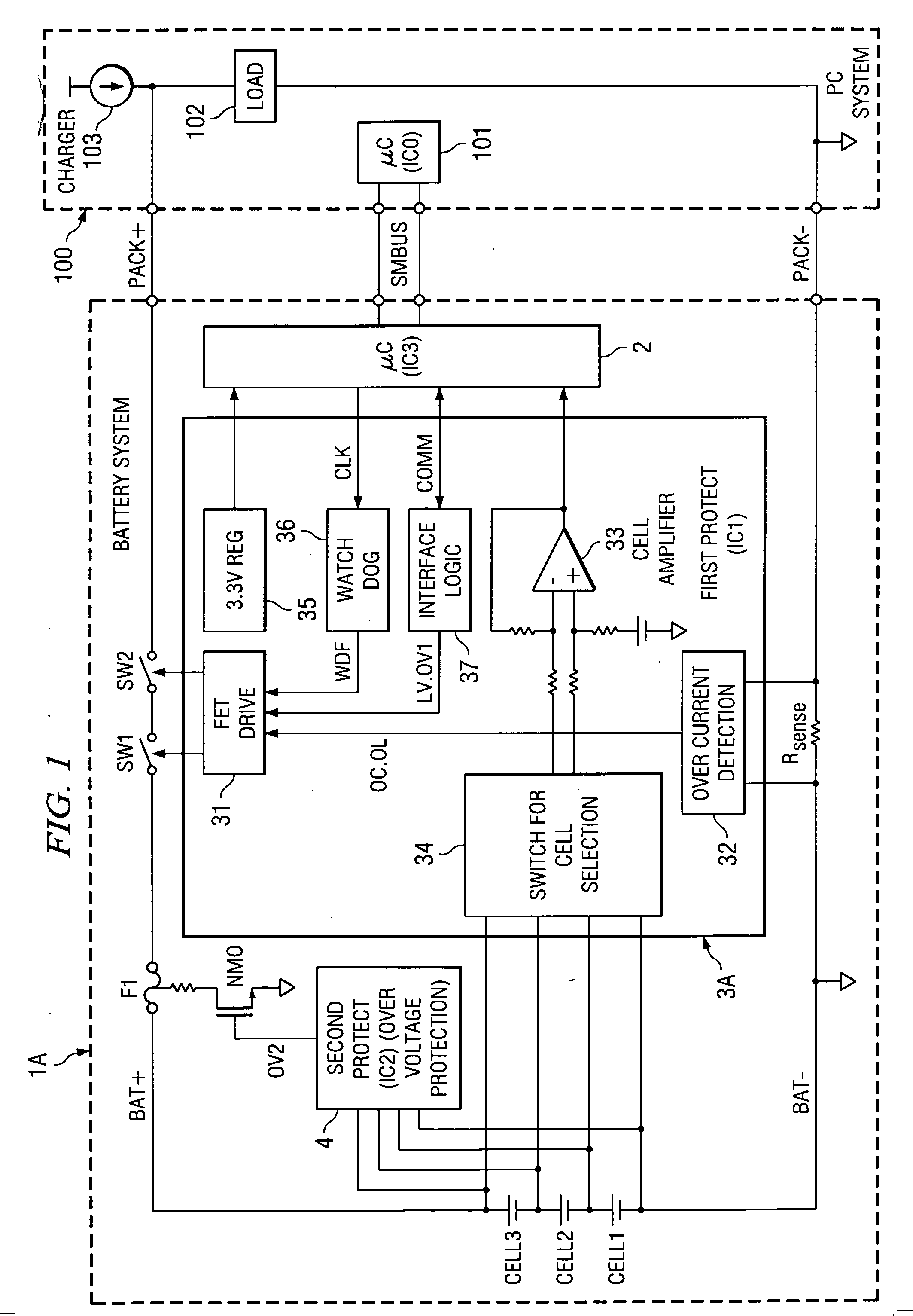
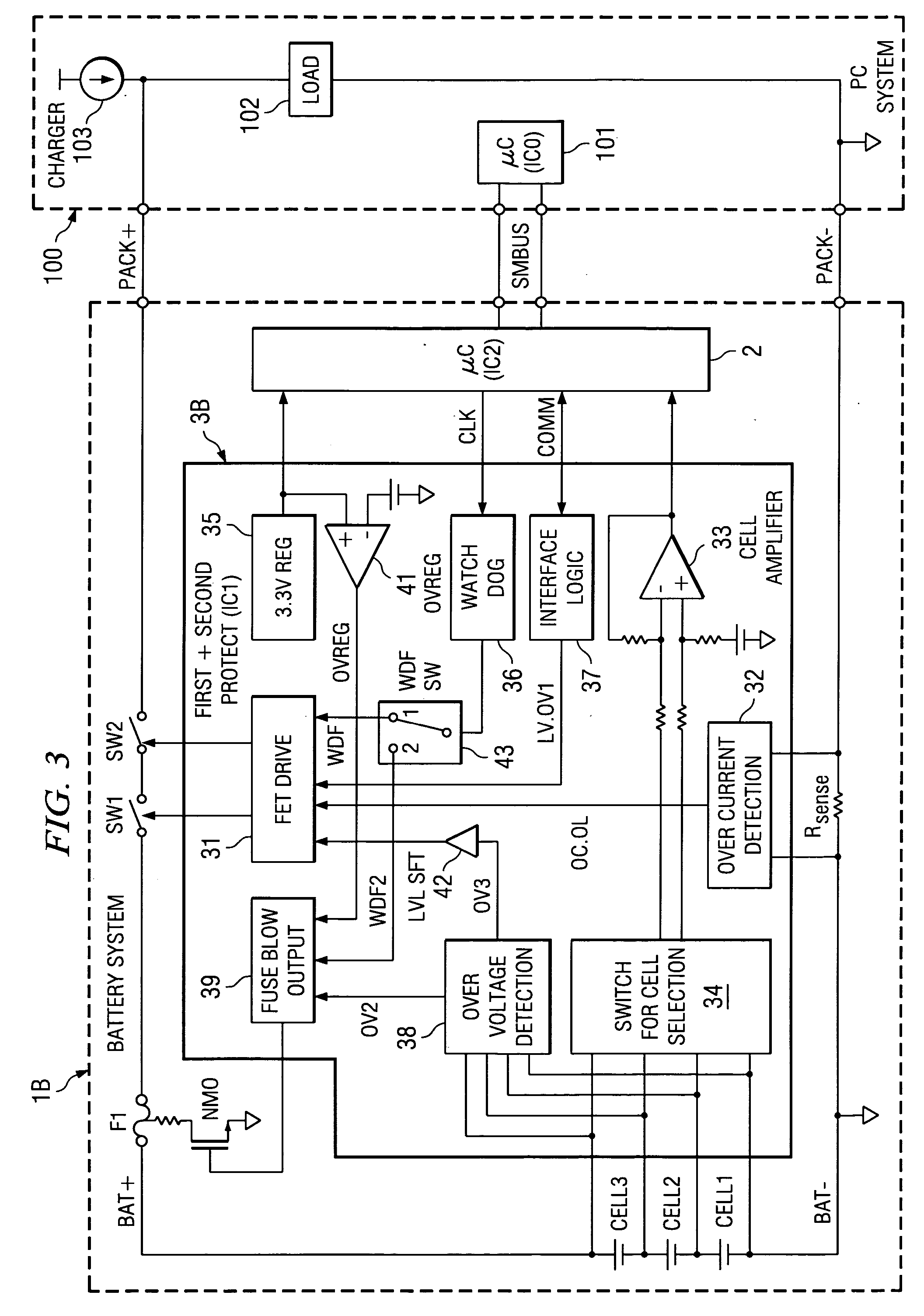
[0030] For the battery protection circuit of the present invention, when secondary protection is performed, because the primary protection has been performed before it, the number of cycles of execution of the secondary protection that cannot be reset can be minimized, so that the operating efficiency can be improved. Also, the interlocked protection operation can be completed by the secondary protection control part (second protecting controller), it is easy to design the operation timing, etc. In addition, the primary protection side and the secondary protection side can work independently, and the primary protection performed from the secondary protection side is separated from the protection performed independently in the primary protection control part (the first protecting controller). Consequently, there is no decrease in the level of protection. On the contrary, it is increased. Also, with system abnormalities also taken into consideration, there is no mutual influence betwe...


PUM


Abstract

A protection of battery system having battery cells Cell1˜Cell3, FET switches SW1, SW2 that are connected to the high-side path and control on/off state of the path, as well as fuse F1 for cutting said path, primary protection circuits 31˜34 that detect abnormalities in charging/discharging of the battery cells and turn the FET switches off, and secondary protecting controller 38 that detect abnormalities in charging/discharging of the battery cells and controls the operation of fuse F1. Secondary protecting controller 38 controls fuse F1 if there is no tendency to a decrease in abnormalities after a prescribed period of time after control of the FET switch.

Description

FIELD OF THE INVENTION [0001] The present invention pertains to a battery protection circuit having a protection function that cuts off the current path when a charge / discharge abnormality in multiple battery cells occurs. BACKGROUND OF THE INVENTION [0002] Battery systems containing lithium ion battery cells or other plural battery cells (secondary battery cells) connected in series are used in various pieces of equipment. Since the battery structure is small but has a high output, a charge / discharge abnormality may take place easily. There are various types of charge / discharge abnormalities, such as rising voltage due to over-charging of the cells, falling voltage due to over-discharge, over-charging current flowing from the external path to the battery cells, over-discharge current flowing from the battery cells to the outside, etc. When such an abnormality takes place, it is necessary to detect it appropriately and to protect the battery cells and the external equipment from ove...

Claims


Application Information

Patent Timeline
Patent Type & Authority Applications(United States)
IPC IPC(8): H02H7/18H02J7/00
CPCH02J7/0031Y02T10/7011H02J2007/0039H02J2007/004B60L3/0046B60L3/04B60L11/1853B60L11/1859B60L11/1861B60L11/1864B60L2240/547B60L2240/549Y02T10/7044Y02T10/7005Y02T10/7061H02J2007/0037B60L58/18B60L58/14B60L58/21B60L58/15H02J7/00304H02J7/00306H02J7/00302Y02T10/70H02H7/18H02H3/087H02H3/044H02H3/05H01M2200/00H01M10/425H01M10/48Y02E60/10H02J7/00308
Inventor YOSHIO, KATSURA
Owner TEXAS INSTR INC
Why Eureka
Try Eureka