
Circuits and methods for providing multiple phase switching regulators which employ the input capacitor voltage signal for current sensing

a technology of voltage signal and input capacitor, which is applied in the direction of efficient power electronics conversion, electric variable regulation, instruments, etc., can solve the problems of significant inequality in load sharing between stages, difficulty in controlling currents in each individual power stage, and increase production costs, so as to achieve efficient load sharing control

Inactive Publication Date: 2005-11-03
ANALOG DEVICES INT UNLTD
View PDF5 Cites 2 Cited by
  • Summary
  • Abstract
  • Description
  • Claims
  • Application Information

AI Technical Summary

Benefits of technology

This approach enables efficient load balancing across multiple phases with reduced dissipative losses, smaller component sizes, lower production costs, and improved power efficiency, as it relies on existing input capacitors for current sensing, minimizing the need for additional components and matching requirements.

Problems solved by technology

One disadvantage of a voltage-mode multiphase switching regulator exists in the difficulty to control currents in each individual power stage.
Slight differences in switch ON-times between phases can result in significant inequality in load sharing between stages.
However, this solution to the power distribution problem increases production costs and reduces power efficiency.
Regulators that utilize sense resistors for balancing inductor current within the individual converter stages, however, still have disadvantages.
For example, current sense resistors cause additional dissipative losses in regulators which, in turn, reduce operating efficiency; the ratio of the power supplied to power provided to a regulator (where a ratio of unity, 1 / 1, is ideal).
Resistors with low resistance values and good matching characteristics, however, are costly and difficult to manufacture.
These regulators also must employ a capacitor, in addition to the sense resistor, for each converter circuit, thereby increasing production costs and design complexity.
Finally, sense resistors are physically large and require valuable circuit board area.
For at least portable product designs, circuit board area is limited, thus limiting the amount of portable applications in which switching regulators with sense resistors may be beneficial.
The matching characteristics, however, of power MOSFET switches are poor, typically having a loose specification in the ±30% range.
Such matching characteristics are significantly worse than those found in sense resistors.
Moreover, there is no guarantee that matching can be achieved between the parts of each individual MOSFET switch.
Such disadvantages make MOSFET sense regulators problematic and deficient.

Method used


Image

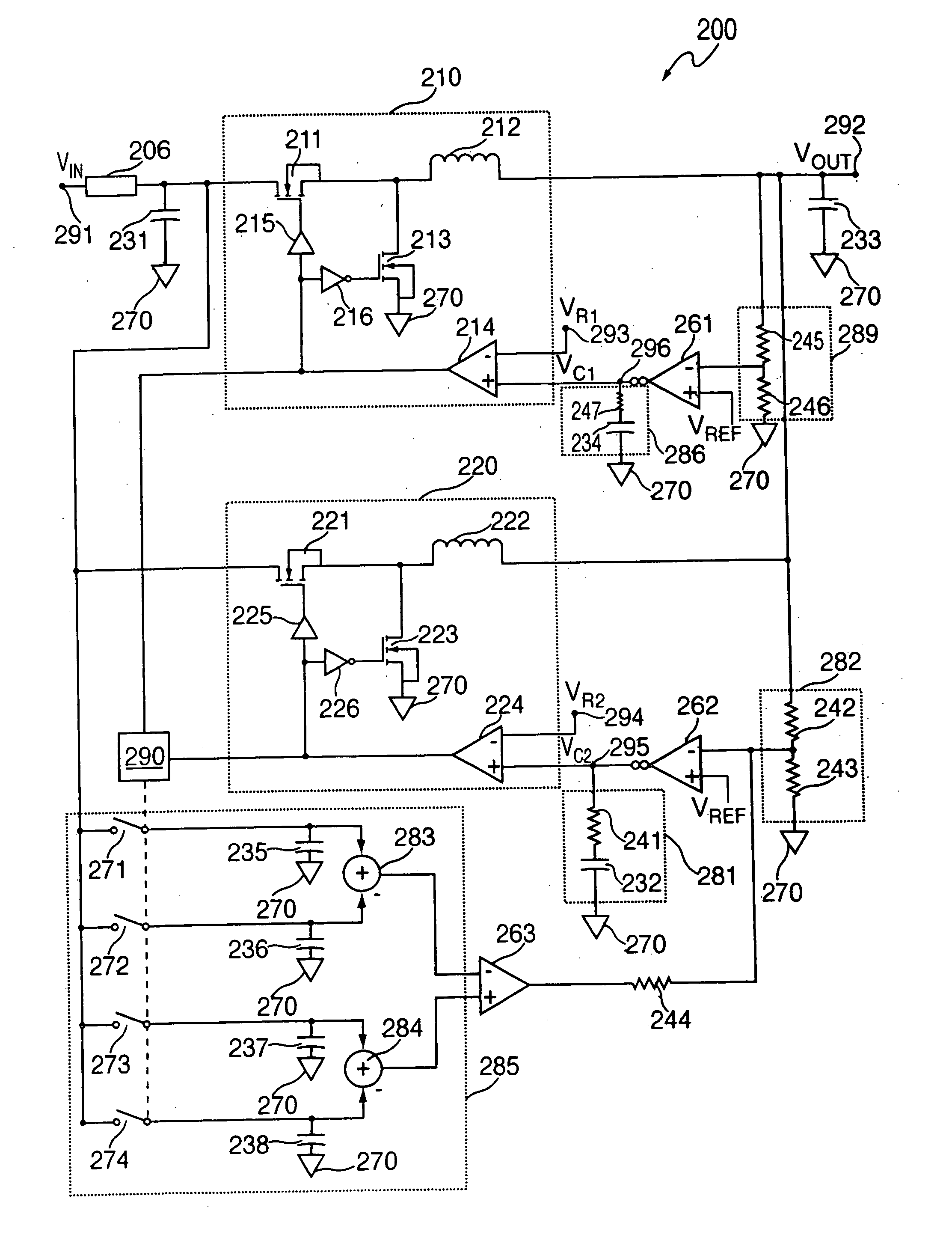
  • Circuits and methods for providing multiple phase switching regulators which employ the input capacitor voltage signal for current sensing
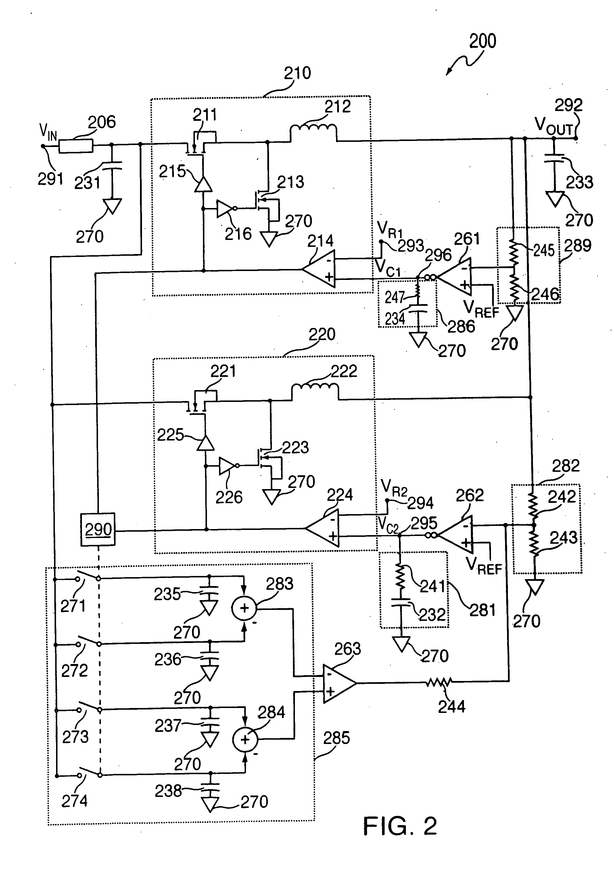
  • Circuits and methods for providing multiple phase switching regulators which employ the input capacitor voltage signal for current sensing
  • Circuits and methods for providing multiple phase switching regulators which employ the input capacitor voltage signal for current sensing

Examples


Embodiment Construction

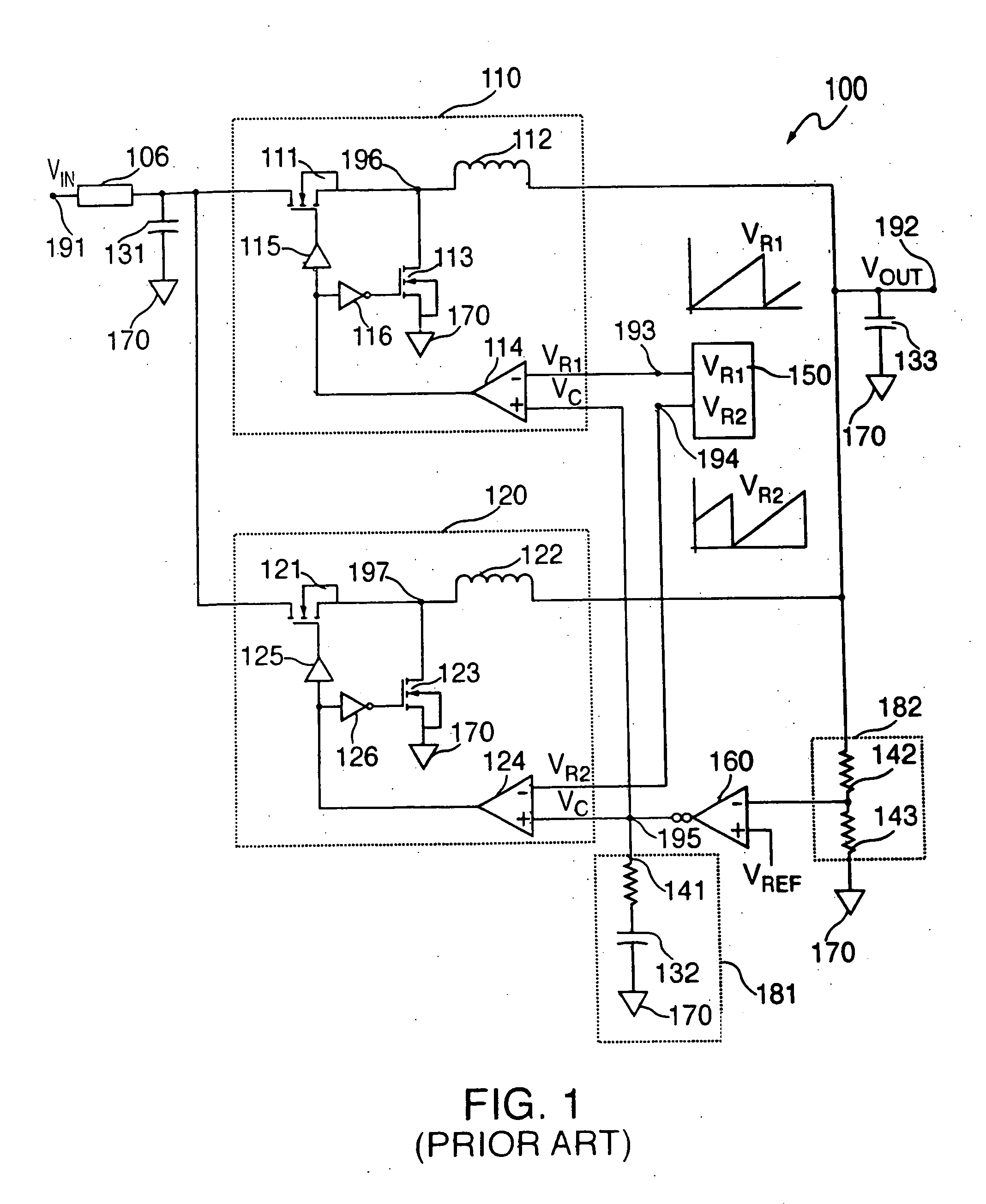
[0019]FIG. 1 shows a prior art two-phase voltage-mode regulator 100. Voltage-mode regulator 100 includes converter stages 110 and 120 and utilizes the common output voltage to control the amount of time, or duty cycle, that the stages' respective main switches 111 and 121 are turned ON. In controlling the amount of time main switches 111 and 121 are turned ON, the amount of current at output node 192 is also controlled.

[0020] Converter circuit 110 operates as described below. At the beginning of each cycle, phase-one ramp output voltage VR1 from ramp generator 150 is reset to zero at node 193 and begins increasing. As a result, the negative input of pulse-width-modulator (PWM) comparator 114 turns LOW (e.g., zero volts). If the negative input voltage of PWM comparator 114 is less than control voltage Vc effecting the positive input of PWM comparator 114 at node 195, the output of PWM comparator 114 turns HIGH (e.g., 5 volts).

[0021] When the output of PWM comparator 114 turns HIGH,...


PUM


Abstract

Circuits and methods to correct the load sharing in multiphase switching regulators are provided. Using these systems and methods, the input capacitor voltage signal can be sampled and used for current sensing of the regulator's stages. Differences in the amount of output current for a converter stage can then be determined. Corrections needed to equalize the output current of the converter stages can then be determined and carried out.

Description

BACKGROUND OF THE INVENTION [0001] This invention relates to circuits and methods that enable multiphase or polyphase switching regulators to evenly divide load current between stages (phases) without the use of a current sense resistance or relying on the analysis of switches such as MOSFET devices. More specifically, this invention relates to systems and methods that monitor the time varying voltage change of the input capacitor in multiphase switching regulators and utilize this monitored value to control load sharing. [0002] DC to DC regulator circuits (power converters) are invaluable in situations where the need is present to regulate an input voltage, such as voltages from household power outlets, for a particular product or application. Power techniques present in such DC to DC regulators can solve the problems surrounding fluctuating and poorly-specified input signals. By producing a desired output voltage, either higher or lower than the regulator's input voltage, DC to DC...

Claims


Application Information

Patent Timeline
Patent Type & Authority Applications(United States)
IPC IPC(8): G05F1/40H02M3/158
CPCH02M3/1584Y02B70/1466H02M2003/1586H02M3/1588H02M3/1586Y02B70/10
Inventor UMMINGER, CHRISTOPHER B.
Owner ANALOG DEVICES INT UNLTD
Learn More