Circuits and methods for providing multiple phase switching regulators which employ the input capacitor voltage signal for current sensing
- Summary
- Abstract
- Description
- Claims
- Application Information
AI Technical Summary
Benefits of technology
Problems solved by technology
Method used
Image
Examples
Embodiment Construction
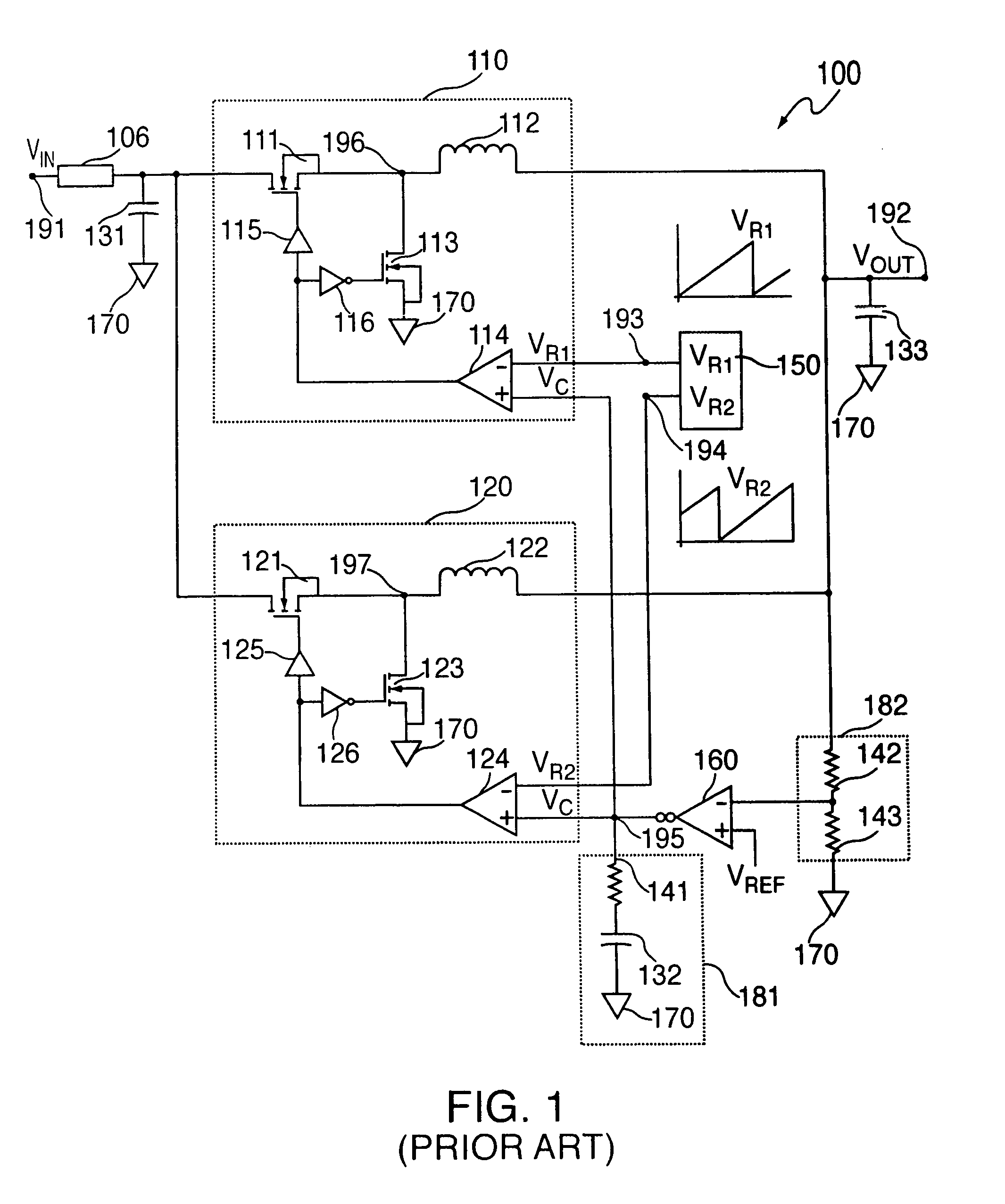
[0019]FIG. 1 shows a prior art two-phase voltage-mode regulator 100. Voltage-mode regulator 100 includes converter stages 110 and 120 and utilizes the common output voltage to control the amount of time, or duty cycle, that the stages' respective main switches 111 and 121 are turned ON. In controlling the amount of time main switches 111 and 121 are turned ON, the amount of current at output node 192 is also controlled.
[0020]Converter circuit 110 operates as described below. At the beginning of each cycle, phase-one ramp output voltage VR1 from ramp generator 150 is reset to zero at node 193 and begins increasing. As a result, the negative input of pulse-width-modulator (PWM) comparator 114 turns LOW (e.g., zero volts). If the negative input voltage of PWM comparator 114 is less than control voltage VC effecting the positive input of PWM comparator 114 at node 195, the output of PWM comparator 114 turns HIGH (e.g., 5 volts).
[0021]When the output of PWM comparator 114 turns HIGH, the...
PUM
 Abstract
Description
Claims
Application Information
 - R&D
- Intellectual Property
- Life Sciences
- Materials
- Tech Scout
- Unparalleled Data Quality
- Higher Quality Content
- 60% Fewer Hallucinations
Browse by: Latest US Patents, China's latest patents, Technical Efficacy Thesaurus, Application Domain, Technology Topic, Popular Technical Reports.
© 2025 PatSnap. All rights reserved.Legal|Privacy policy|Modern Slavery Act Transparency Statement|Sitemap|About US| Contact US: help@patsnap.com


